

Modifications for the ICOM - RogerK
Modifications for the ICOM - RogerK
Modifications for the ICOM - RogerK
- No tags were found...

You also want an ePaper? Increase the reach of your titles
YUMPU automatically turns print PDFs into web optimized ePapers that Google loves.
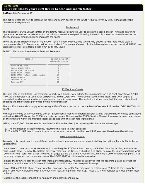
19-07-1998(R-7000) Modify your <strong>ICOM</strong> R7000 to scan and search fasterAuthor: Bob Parnass, AJ9SThis article describes how to increase <strong>the</strong> scan and search speeds of <strong>the</strong> <strong>ICOM</strong> R7000 receiver by 60% without noticeableper<strong>for</strong>mance degradation.BackgroundThe front panel SCAN SPEED control on <strong>the</strong> R7000 receiver allows <strong>the</strong> user to adjust <strong>the</strong> speed of scan- ning and searchingoperations, as well as <strong>the</strong> rate at which <strong>the</strong> priority channel is sampled. Rotating <strong>the</strong> control counterclockwise decreases <strong>the</strong>speed, and rota- ting it clockwise increases <strong>the</strong> speed.When <strong>the</strong> SCAN SPEED control on my R7000 (serial number 001400) was turned fully clockwise, <strong>the</strong> radio would scan amaximum of about 8 channels/second, or search about 8 increments/second. As <strong>the</strong> following table shows, <strong>the</strong> stock R7000 canscan about as fast as a Radio Shack PRO-30 or PRO-2003.TABLE 1. Maximum Scan Rates of Selected Receivers_____________________________________________________| Scanner Maximum Scan Rate|| | (channels/second)||________________________________|___________________|| Kenwood TR-2600 | 1.2 || Radio Shack PRO-30 | 8 || Radio Shack PRO-2003 | 8 || <strong>ICOM</strong> R7000 (stock) | 8 || <strong>ICOM</strong> R7000 (after modification)| 13 || Regency M400 | 13 || Bearcat 20/20 | 15 || Bearcat 300 | 15 ||________________________________|___________________|R7000 Scan CircuitsThe scan rate of <strong>the</strong> R7000 is determined, in part, by a simple clock outside <strong>the</strong> microprocessor. The front panel SCAN SPEEDrheostat and resistor R18 (and o<strong>the</strong>r components in <strong>the</strong> LOGIC UNIT) control <strong>the</strong> speed of this clock. The clock output isconnected to what appears to be an input port on <strong>the</strong> microprocessor. The upshot is that we can affect <strong>the</strong> scan rate withoutaffecting <strong>the</strong> o<strong>the</strong>r chores per<strong>for</strong>med by <strong>the</strong> microprocessor.The modification consists simply of soldering a 470,000 ohm resistor across <strong>the</strong> leads of resistor R18 on <strong>the</strong> LOGIC UNIT circuitboard.How was <strong>the</strong> value of 470,000 ohms chosen? Experimenta- tion with different resistor values showed that <strong>for</strong> values both aboveand below 470,000 ohms, <strong>the</strong> R7000 scan rate decreases. Not having <strong>the</strong> R7000 Service Manual, I assume this can be explainedby <strong>the</strong> firmware within <strong>the</strong> microprocessor associated with <strong>the</strong> scan rate input port.2Adding <strong>the</strong> 470,000 ohm resistor in parallel with R18, ra<strong>the</strong>r than just replacing R18, has a few advantages:1. The modification is easily undone, returning <strong>the</strong> radio to stock condition.2. The LOGIC UNIT board does not have to be removed, as would be <strong>the</strong> case if R18 was unsoldered from <strong>the</strong> foil side.Making <strong>the</strong> ModificationAccessing this circuit board is not difficult, and involves <strong>the</strong> same steps used when installing <strong>the</strong> optional Remote Controller orSpeech units.Use a towel to cover your work area to avoid scratching <strong>the</strong> R7000 cabinet. Unplug <strong>the</strong> R7000 from <strong>the</strong> AC line, and turn <strong>the</strong>radio upside down. Remove <strong>the</strong> bottom cover by removing <strong>the</strong> 12 screws holding it in place. Remove <strong>the</strong> 4 screws holding what<strong>ICOM</strong> terms <strong>the</strong> "parti- tion panel". Pictures on pages 32 and 34 of <strong>the</strong> R7000 Instruction Manual show <strong>the</strong> partition panel. Afterremoving this panel, <strong>the</strong> component side of <strong>the</strong> LOGIC UNIT circuit board is accessible.Perhaps <strong>the</strong> firmware polls <strong>the</strong> scan rate input port infrequently. Ano<strong>the</strong>r possibility is that <strong>the</strong> scanning pulses interrupt <strong>the</strong>processor, and <strong>the</strong> interrupt firmware is limited in its ability to process frequent interrupts.Locate R18, a 270,000 ohm 1/8 watt resistor, near con- nector J5. You may wish to remove plug P5 from J5 tem- porarily if itgets in your way. Carefully solder a 470,000 ohm resistor in parallel with R18. I used a 1/4 watt resistor as it was <strong>the</strong> smalleston hand.Reassemble <strong>the</strong> radio, connect it to AC power and antenna, and enjoy.


