Digital Servo Amplifier SERVOSTAR 400 - BIBUS SK, sro
Digital Servo Amplifier SERVOSTAR 400 - BIBUS SK, sro
Digital Servo Amplifier SERVOSTAR 400 - BIBUS SK, sro

You also want an ePaper? Increase the reach of your titles
YUMPU automatically turns print PDFs into web optimized ePapers that Google loves.
Interfaces 07/03 Kollmorgen<br />
3.6.2 SSI interface (X4)<br />
The SSI interface (synchronous serial absolute-encoder emulation) is part of the package delivered.<br />
Select the encoder function SSI (screen page Encoder).<br />
In the servo amplifier, the position of the motor shaft is calculated from the cyclic-absolute signals of<br />
the resolver or encoder. The information is used to generate a position output compatible with the<br />
data format of normal commercial SSI absolute encoders. This synchronous-serial, cyclic-absolute<br />
12-bit information is output on the SubD-Connector X4.<br />
24 bits are transmitted. The upper 12 bits are fixed at ZERO, the lower 12 bits contain the position<br />
information.<br />
The interface must be read in as a multi-turn encoder, but delivers valid single-turn data. The signal<br />
sequence can be output in Gray code (standard) or in binary code (parameter SSI-CODE).<br />
A serial signal is read out from the control, with a synchronous clock frequency of max. 1.5 MHz.<br />
The servo amplifier can be adjusted to the clock frequency of your SSI-evaluation with the<br />
SSI-CLOCK parameter (200 kHz or 1.5MHz and inverted).<br />
The ground reference for the interface is AGND.<br />
This must always be connected to the ground for the control input signals.<br />
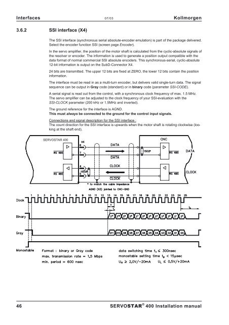
Connections and signal description for the SSI interface :<br />
The count direction for the SSI interface is upwards when the motor shaft is rotating clockwise (looking<br />
at the shaft end).<br />
<strong>SERVOSTAR</strong> <strong>400</strong><br />
46 <strong>SERVOSTAR</strong> ® <strong>400</strong> Installation manual