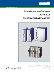
Digital Servo Amplifier SERVOSTAR 400 - BIBUS SK, sro
Digital Servo Amplifier SERVOSTAR 400 - BIBUS SK, sro
Digital Servo Amplifier SERVOSTAR 400 - BIBUS SK, sro
Create successful ePaper yourself
Turn your PDF publications into a flip-book with our unique Google optimized e-Paper software.
Interfaces 07/03 Kollmorgen<br />
3.10 Fieldbus connection<br />
3.10.1 CANopen interface (X7)<br />
The interface for connection to the CAN bus (default: 500 kbps). The integrated profile is based on<br />
the communication profile CANopen DS301 and the drive profile DSP402.<br />
The following functions are available in connection with the integrated position controller:<br />
Jogging with variable speed, homing, start motion task, start direct task, digital setpoint provision,<br />
data transmission functions and many others.<br />
Detailed information can be found in the CANopen manual.<br />
The interface is at the same potential as the internal logic, and uses AGND as the ground reference.<br />
The analog input can still be used.<br />
Even if the analog input is not used, AGND must nevertheless be joined to the control system<br />
ground!<br />
<strong>SERVOSTAR</strong> <strong>400</strong><br />
CAN bus cable<br />
To meet ISO 11898 you should use a bus cable with a 120 � characteristic impedance. The maximum<br />
usable cable length for reliable communication decreases with increasing transmission speed.<br />
As a guide, you can use the following values which we have measured, but they must not be assumed<br />
to be limits:<br />
Cable data: Characteristic impedance 100-120 �<br />
Cable capacitance max. 60 nF/km<br />
Conductor loop resistance 159.8 �/km<br />
Cable length, depending on the transmission rate<br />
Transmission rate / kbps max. cable length / m<br />
1000 20<br />
500 70<br />
250 115<br />
Lower cable capacitance (max. 30 nF/km) and lower lead resistance (loop: 115 �/km) make it possible<br />
to transmit over longer distances.<br />
(Characteristic impedance 150 ± 5� �terminating resistance 150 ± 5�).<br />
For EMC reasons, the SubD connector housing must fulfil the following conditions:<br />
— metal or metallized housing<br />
— provision for connecting the cable shielding within the housing,<br />
large-area connections<br />
The master is fitted with a CAN input. All axis modules in the system are connected to this through<br />
the internal bus. The last axis module has a CAN output, where the CAN bus either continues to<br />
other bus participants or is terminated by a termination resistor.<br />
52 <strong>SERVOSTAR</strong> ® <strong>400</strong> Installation manual


