TMS320VC5409 Fixed-Point Digital Signal ... - Texas Instruments
TMS320VC5409 Fixed-Point Digital Signal ... - Texas Instruments
TMS320VC5409 Fixed-Point Digital Signal ... - Texas Instruments
- No tags were found...

You also want an ePaper? Increase the reach of your titles
YUMPU automatically turns print PDFs into web optimized ePapers that Google loves.
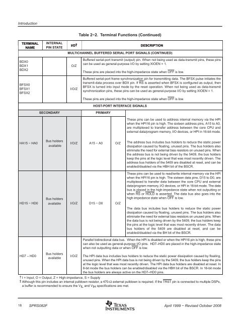
IntroductionTERMINALNAMEINTERNALPIN STATETable 2−2. Terminal Functions (Continued)I/O†DESCRIPTIONMULTICHANNEL BUFFERED SERIAL PORT SIGNALS (CONTINUED)BDX0BDX1BDX2BFSX0BFSX1BFSX2O/ZI/O/ZBuffered serial-port transmit (output) pin. When not being used as data-transmit pins, these pinscan be used as general-purpose I/O by setting XIOEN = 1.These pins are placed into the high-impedance state when OFF is low.Buffered serial-port frame synchronization pin for transmitting data. The BFSX pulse initiates thetransmit-data process over BDX pin. If RS is asserted when BFSX is configured as output, thenBFSX is turned into input mode by the reset operation. When not being used as data-transmitsynchronization pins, these pins can be used as general-purpose I/O by setting XIOEN = 1.These pins are placed into the high-impedance state when OFF is low.HOST-PORT INTERFACE SIGNALSSECONDARYPRIMARYThese pins can be used to address internal memory via the HPIwhen the HPI16 pin is high. The sixteen address pins, A15 to A0,are multiplexed to transfer address between the core CPU andexternal data/program memory, I/O devices, or HPI in 16-bit mode.HA15 − HA0Bus holdersavailableI/O/Z A15 − A0 O/ZThe address bus includes bus holders to reduce the static powerdissipation caused by floating, unused pins. The bus holders alsoeliminate the need for external bias resistors on unused pins. Whenthe address bus is not being driven by the 5409, the bus holderskeep the pins at the logic level that was most recently driven. Theaddress bus holders of the 5409 are disabled at reset, and can beenabled/disabled via the HBH bit of the BSCR.HD15 − HD0Bus holdersavailable I/O/Z D15 − D0 O/ZThese pins can be used to read/write internal memory via the HPIwhen the HPI16 pin is high. The sixteen data pins, D15 to D0, aremultiplexed to transfer data between the core CPU and externaldata/program memory, I/O devices, or HPI in 16-bit mode. The databus is placed in the high-impedance state when not outputting orwhen RS or HOLD is asserted. The data bus also goes into thehigh-impedance state when OFF is low.The data bus includes bus holders to reduce the static powerdissipation caused by floating, unused pins. The bus holders alsoeliminate the need for external bias resistors on unused pins. Whenthe data bus is not being driven by the 5409, the bus holders keepthe pins at the logic level that was most recently driven. The databus holders of the 5409 are disabled at reset, and can beenabled/disabled via the BH bit of the BSCR.HD7 – HD0Bus holdersavailableI/O/ZParallel bidirectional data bus. When the HPI is disabled or when the HPI16 pin is high, these pinscan also be used as general-purpose I/O pins. HD7–HD0 are placed in the high-impedance statewhen not outputting data or when OFF is low.The HPI data bus includes bus holders to reduce the static power dissipation caused by floating,unused pins. When the HPI data bus is not being driven by the 5409, the bus holders keep the pinsat the logic level that was most recently driven. The HPI data bus holders are disabled at reset. In8-bit mode the bus holders can be enabled/disabled via the HBH bit of the BSCR. In 16-bit modethe bus holders are always active on the HD7–HD0 pins.† I = Input, O = Output, Z = High-impedance, S = Supply‡ Although this pin includes an internal pulldown resistor, a 470-Ω external pulldown is required. If the TRST pin is connected to multiple DSPs,a buffer is recommended to ensure the VIL and VIH specifications are met.18 SPRS082FApril 1999 − Revised October 2008