TMS320VC5409 Fixed-Point Digital Signal ... - Texas Instruments
TMS320VC5409 Fixed-Point Digital Signal ... - Texas Instruments
TMS320VC5409 Fixed-Point Digital Signal ... - Texas Instruments
- No tags were found...

You also want an ePaper? Increase the reach of your titles
YUMPU automatically turns print PDFs into web optimized ePapers that Google loves.
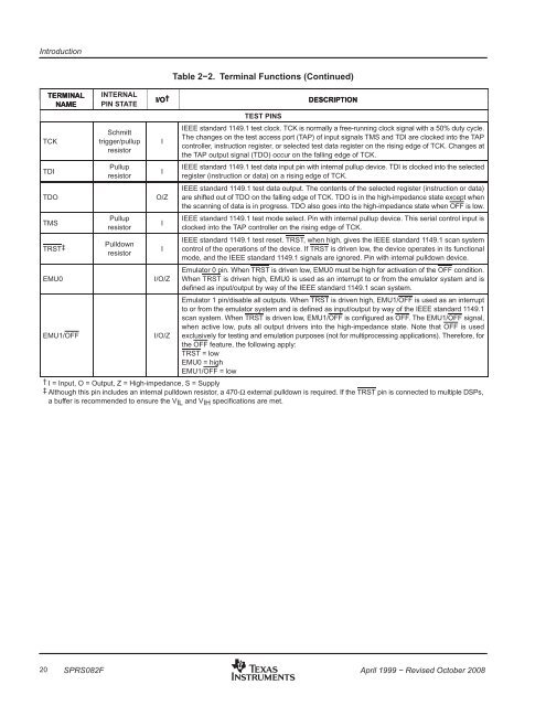
IntroductionTERMINALNAMETCKTDITDOTMSTRST‡EMU0EMU1/OFFINTERNALPIN STATESchmitttrigger/pullupresistorPullupresistorPullupresistorPulldownresistorI/O†IIO/ZIII/O/ZI/O/ZTable 2−2. Terminal Functions (Continued)DESCRIPTIONTEST PINSIEEE standard 1149.1 test clock. TCK is normally a free-running clock signal with a 50% duty cycle.The changes on the test access port (TAP) of input signals TMS and TDI are clocked into the TAPcontroller, instruction register, or selected test data register on the rising edge of TCK. Changes atthe TAP output signal (TDO) occur on the falling edge of TCK.IEEE standard 1149.1 test data input pin with internal pullup device. TDI is clocked into the selectedregister (instruction or data) on a rising edge of TCK.IEEE standard 1149.1 test data output. The contents of the selected register (instruction or data)are shifted out of TDO on the falling edge of TCK. TDO is in the high-impedance state except whenthe scanning of data is in progress. TDO also goes into the high-impedance state when OFF is low.IEEE standard 1149.1 test mode select. Pin with internal pullup device. This serial control input isclocked into the TAP controller on the rising edge of TCK.IEEE standard 1149.1 test reset. TRST, when high, gives the IEEE standard 1149.1 scan systemcontrol of the operations of the device. If TRST is driven low, the device operates in its functionalmode, and the IEEE standard 1149.1 signals are ignored. Pin with internal pulldown device.Emulator 0 pin. When TRST is driven low, EMU0 must be high for activation of the OFF condition.When TRST is driven high, EMU0 is used as an interrupt to or from the emulator system and isdefined as input/output by way of the IEEE standard 1149.1 scan system.Emulator 1 pin/disable all outputs. When TRST is driven high, EMU1/OFF is used as an interruptto or from the emulator system and is defined as input/output by way of the IEEE standard 1149.1scan system. When TRST is driven low, EMU1/OFF is configured as OFF. The EMU1/OFF signal,when active low, puts all output drivers into the high-impedance state. Note that OFF is usedexclusively for testing and emulation purposes (not for multiprocessing applications). Therefore, forthe OFF feature, the following apply:TRST = lowEMU0 = highEMU1/OFF = low† I = Input, O = Output, Z = High-impedance, S = Supply‡ Although this pin includes an internal pulldown resistor, a 470-Ω external pulldown is required. If the TRST pin is connected to multiple DSPs,a buffer is recommended to ensure the VIL and VIH specifications are met.20 SPRS082FApril 1999 − Revised October 2008