TMS320VC5409 Fixed-Point Digital Signal ... - Texas Instruments
TMS320VC5409 Fixed-Point Digital Signal ... - Texas Instruments
TMS320VC5409 Fixed-Point Digital Signal ... - Texas Instruments
- No tags were found...

Create successful ePaper yourself
Turn your PDF publications into a flip-book with our unique Google optimized e-Paper software.
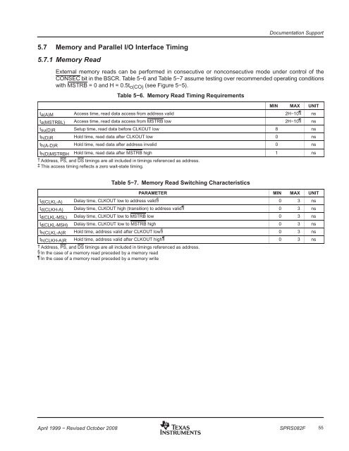
Documentation Support5.7 Memory and Parallel I/O Interface Timing5.7.1 Memory ReadExternal memory reads can be performed in consecutive or nonconsecutive mode under control of theCONSEC bit in the BSCR. Table 5−6 and Table 5−7 assume testing over recommended operating conditionswith MSTRB = 0 and H = 0.5t c(CO) (see Figure 5−5).Table 5−6. Memory Read Timing RequirementsMIN MAX UNITta(A)M Access time, read data access from address valid 2H−10 nsta(MSTRBL) Access time, read data access from MSTRB low 2H−10 nstsu(D)R Setup time, read data before CLKOUT low 8 nsth(D)R Hold time, read data after CLKOUT low 0 nsth(A-D)R Hold time, read data after address invalid 0 nsth(D)MSTRBH Hold time, read data after MSTRB high 1 ns† Address, PS, and DS timings are all included in timings referenced as address.‡ This access timing reflects a zero wait-state timing.Table 5−7. Memory Read Switching CharacteristicsPARAMETER MIN MAX UNITtd(CLKL-A) Delay time, CLKOUT low to address valid§ 0 3 nstd(CLKH-A) Delay time, CLKOUT high (transition) to address valid 0 3 nstd(CLKL-MSL) Delay time, CLKOUT low to MSTRB low 0 3 nstd(CLKL-MSH) Delay time, CLKOUT low to MSTRB high 0 3 nsth(CLKL-A)R Hold time, address valid after CLKOUT low§ 0 3 nsth(CLKH-A)R Hold time, address valid after CLKOUT high 0 3 ns† Address, PS, and DS timings are all included in timings referenced as address.§ In the case of a memory read preceded by a memory read In the case of a memory read preceded by a memory writeApril 1999 − Revised October 2008SPRS082F55