Ninth International Conference on Permafrost ... - IARC Research
Ninth International Conference on Permafrost ... - IARC Research
Ninth International Conference on Permafrost ... - IARC Research

Create successful ePaper yourself
Turn your PDF publications into a flip-book with our unique Google optimized e-Paper software.
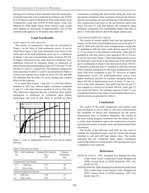
Ni n t h In t e r n at i o n a l Co n f e r e n c e o n Pe r m a f r o s tspacing of 6 m (about 4 helix diameter from the tested pile).Axial pile load tests were c<strong>on</strong>ducted according to the ASTMD-1143 Quick Load Test Method for Piles under Static AxialCompressive Load and ASTM D-3689 Quick Load TestMethod for Piles under Static Axial Tensile Load. Loadswere applied in increments of approximately 10% of theestimated pile capacity in 10-minute time intervals.Load Test ResultsAxial compressive pile capacitiesThe results of compressive load tests are presented inFigure 1 in the form of load settlement curves. It can benoted from Figure 1 that load settlements were linear at theinitial part of the load-settlement curve up to a settlementof about 3 mm and corresp<strong>on</strong>ding loads of about 200 kN.At higher settlement levels, piles showed a n<strong>on</strong>linear loadsettlementfollowed by plunging failure at settlement ofabout 50 mm and corresp<strong>on</strong>ding loads of 677 kN and 772 kNfor piles C1 and C2, respectively. The ultimate compressiveload capacities for piles C1 and C2 are presented in Table 3.Cycles were carried out at loads of about 245 kN, and 490kN indicated that the effect of cyclic loading had a minoreffect <strong>on</strong> the resp<strong>on</strong>se.It is noted from Figure 1 that pile C2 with four helixesinstalled in stiff clay offered higher resistance comparedto pile C1 with triple helixes installed in soft to firm clay.This behaviour suggested that the cylindrical shear failuremechanism is mobilized. In cylindrical shear failuremechanism, the load at pile head is resisted by threeLoad (kN)500.0400.0300.0200.0100.00.0Triple Helixes Pile T1, Stiff Clay,S/D = 2.5Triple Helixes Pile T2, Soft to Firm Clay, S/D = 30 2 4 6 8 10 12 14 16 18 20Settlement (mm)Figure 2. Load vs. displacement curves for axial tensi<strong>on</strong> (uplift)load tests.Table 3. Pile load test results.PileNoSoil C<strong>on</strong>diti<strong>on</strong>sCompressi<strong>on</strong> Test ResultsUltimate Pile Capacity(Q ult)kNUltimateSettlementmmC1 Stiff clay 677 50C2 Soft to firm 772 50Tensi<strong>on</strong> (Uplift) Test ResultsT1 Stiff clay 370 15T2 Soft to firm 445 15comp<strong>on</strong>ents including the skin fricti<strong>on</strong> al<strong>on</strong>g the shaft, thedeveloped cylindrical shear resistance between the helixes,and the surrounding soil and end bearing of the bottom helix(for compressi<strong>on</strong> load tests) or the top helix(for uplift loadtests). For pile C2 with four helixes, the cylindrical shearresistance comp<strong>on</strong>ent was c<strong>on</strong>siderably higher than that ofpile C1 with triple helixes due to the larger surface area.Axial tensi<strong>on</strong> (uplift) pile capacityThe results of tensile (uplift) load tests are presented inFigure 2 in the form of load displacement curves for piles T1and T2. Both piles had the same c<strong>on</strong>figurati<strong>on</strong>s, except pileT1 installed in stiff clay had a triple helixes spaced at 2.5D(1.77 m), where D is the diameter of the helix, while pile T2installed in soft clay helixes were spaced at 3D (2.134 m).It can be seen from Figure 2 that load displacement curvesfor both piles were linear at the initial part of the uplift loadup to a settlement of about 1 mm and load of about 100 kN.It should be noted that pile T1 installed in stiff clay showedsofter resp<strong>on</strong>se manifested by the larger displacement at thesame load level compared to pile T2. However at higherdisplacement levels, the load-displacement curves werehighly n<strong>on</strong>linear, and pile T2 reached a plunging failure ofabout 445 kN at displacement level of about 15 mm (i.e.,2.5% of the helix diameter). The uplift load test for pile T1was stopped at a load level of about 300 kN, while pile T2was tested till failure. The ultimate capacity of pile T1 wasextrapolated based <strong>on</strong> the shape of load-displacement curve,and the results are presented in Table 3.C<strong>on</strong>clusi<strong>on</strong>sThe results of the axial compressi<strong>on</strong> and tensi<strong>on</strong> loadtests performed in soft to firm or stiff clays dem<strong>on</strong>stratedthe suitability of helical pile foundati<strong>on</strong>s for the powertransmissi<strong>on</strong> lines in Northern Manitoba. The results ofthe load testing program c<strong>on</strong>firmed that the helical pile isa viable deep foundati<strong>on</strong> opti<strong>on</strong> for c<strong>on</strong>structi<strong>on</strong> of powertransmissi<strong>on</strong> towers in remote areas and dem<strong>on</strong>strated theiradvantages.The results of the full-scale load tests are also used tovalidate the theoretical model used for helical pile designinstalled in soft and stiff high plastic clays. The resultsindicated that the cylindrical shear failure mechanismc<strong>on</strong>trols the behavior of helical piles with spacing ratio up to3 installed in clay materials.ReferencesASTM D 1143-81. 1981. Standard Test Method for PilesUnder Static Axial Compressive Load (Reapproved1994). Annual Book of ASTM Standards 1997, Vol.04.08: 95-105.ASTM D 3689-90. 1990. Standard Test Method for IndividualPiles Under Static Axial Tensile Load; (Reapproved1995). Annual Book of ASTM Standard, 1997, Vol.04.08: 366-375.262