Downloaded from http://www.everyspec.<strong>com</strong> on 2011-10-29T14:56:01.DOD-HDBK-791(AM)6-3..3 EQUIPMENT FUNCTIONAL AND/ORINSTRUCTIONAL MARKINGSNo specific guidelines or criteria exist for determiningwhen to install functional and or instructional markingson equipment. Instruction plates are not required whenthe steps to be taken are obvious to the average mechanic.Conversely, instructions should be provided when it isdetermined that a technician trained on past equipmentwould have a high risk of error if he applied the samemaintenance procedures to the new equipment. Accordingly,each equipment item should be evaluated carefullyto determine what instructions are required and theproper content of these instructions. It is safer to overinstructthan to underinstruct. Basically, the decisioninvolves the evaluation of the anticipated maintenanceoperation to determine what information the technicianrequires. For example, a simple operation such as changinga drive belt should be illustrated if the belt is crossedover. If reference to data can be eliminated by placingsimple instructions on the equipment, an instruction plateor diagram is warranted. Areas that merit considerationare basic operating instructions; calibration data; simplewiring or fluid flow diagrams; adjustment instructions;location of test points: location of piece parts on electroniccircuit cards; valve and ignition settings; types offuel, oil, and lubricant to be used; and other data requiredto perform routine servicing and maintenance. Guidelinesfor the placement of instruction plates are provided inpar. 6-5.2.When considered important, the identification of pertinentdata with regard to function, capacity, capabilities.limits, ranges, frequencies, voltage, current. power, revolutionsper minute, weight, etc., should be indicated. Thedata may be displayed on a separate plate or integratedwith the nomenclature plate as shown in Fig. 6-1. To becurrent on instruction plate identification, consult thelatest revision of MIL-P-514 ( Ref. 6).6-3.4 HAZARDOUS CONDITIONMARKINGSHazards and associated risks should be eliminated bydesign wherever possible. Components should be locatedso that required access during operation, servicing, maintenance,or adjustment minimizes personnel exposure tohazards. When alternate design approaches cannot eliminatethe hazard, only then should warning and cautionlabels be displayed (Ref. 7). The use of warning andcaution markings should not be used as a substitute forproper engineering design.Hardware, per se, is not the only source of hazards. Ananalysis of work areas and maintenance operationsshould be made by human factors personnel and industrialsafety personnel to identify hazards that may resultfrom unsafe acts by technicians and maybe introduced bysigns is1. Install appropriate labels to remind the technicianthat he must consult a technical manul be before workingon equipment.2. Erect high visibility warnings it peronnel maybe subjected to harmful gases. noise levels, or suddenincreases or decrcases in pressure, laser beams, electromagneticradiation, or nuclear radiation.3. Identity areas of operation or maintenance inwhich special protective clothing, tools, or equipmente.g., insulated shoes, gloves, suits, hard hats, and orbreathing masks are necessary.4. Mark all electrical receptacles with their voltage,phase, and frequency characteristics, as appropriate; specificdetails are contained in MIL-STD-454 (Ref. 8).5. For aircraft, missile, and space sytems clearlyand unambiguously label pipe, hose, and tubing for fluids(gas, steam, hydraulic fluids), and label or code them as tocontents. pressure, heat, cold, or other hazardous propertiesin accordance with MIL-STD-1247 (Ref. 9). Markand color code pipelines for other systems in accordancewith MIL-STD-101 (Ref. 10).6. Provide “NO STEP” markings where necessaryto prevent injury to personnel or damage to equipment.7. Labeljacking and hoisting points conspicuouslyand unambiguous). and describe any special handlingrequirements for these operations.8. Distinctly mark the center of gravity and theweight of equipment where applicable.9. Indicate weight capacity on stands, hoists,cranes, lilts, jacks, and similar weight-bearing equipmentto prevent overloading.10. Prominently display labels instructing the technicianin hazardous situations, for example, instructionsfor sequential operations as shown in Fig. 6-3 (Ref. 11).11. Make caution and warning signs as informativeas possible, yet they should be consistent with limits oninformation required and space available (see Fig. 6-4).The content of the label will vary, but it should informpersonnela. Why a hazardous condition existsb. Places to avoidc. Behavior to avoidd. Sequence to follow to obviate a dangere. Where to refer for additional specific information.The language level of the signs should be consistent withthe reading level of the target audience.6-.3.5 PART IDENTIFICATIONIdentification is essential throughout the life of anypart. The nomenclature, with its associated number6-4
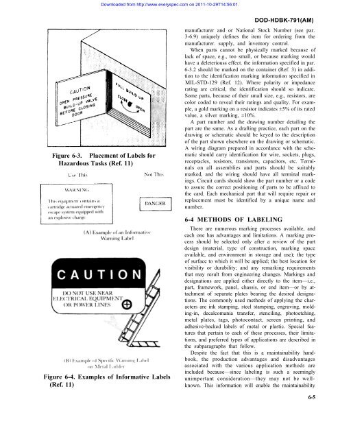
Downloaded from http://www.everyspec.<strong>com</strong> on 2011-10-29T14:56:01.Figure 6-3. Placement of Labels forHazardous Tasks (Ref. 11)Figure 6-4. Examples of Informative Labels(Ref. 11)DOD-HDBK-791(AM)manufacturer and or National Stock Number (see par.3-6.9) uniquely defines the item for ordering from themanufacturer. supply, and inventory control.When parts cannot be physically marked because oflack of space, e.g., too small, or because marking wouldhave a deleteriouss effect. the information specified in par.6-3.2 should be marked on the container (Ref. 3) in additionto the identification marking information specified inMIL-STD-129 (Ref. 12). Where polarity or impedancerating are critical, the identification should so indicate.Some parts, because of their small size, e.g., resistors, arecolor coded to reveal their ratings and quality. For example,a gold marking on a resistor indicates ±5% of its ratedvalue, a silver marking, ±10%.A part number and the drawing number detailing thepart are the same. As a drafting practice, each part on thedrawing or schematic should be keyed to the descriptionof the part shown elsewhere on the drawing or schematic.A wiring diagram prepared in accordance with the schematicshould carry identification for wire, sockets, plugs,receptacles, resistors, transistors, capacitors, etc. Terminalson all assemblies and parts should be suitablymarked, and the wiring should have all terminal markings.Circuit cards should show the part number or a codeto assure the correct positioning of parts to be affixed tothe card. Each mechanical part that will require repair orreplacement must be identified by a unique name andnumber.6-4 METHODS OF LABELINGThere are numerous marking processes available, andeach one has advantages and limitations. A marking processshould be selected only after a review of the partdesign (material, type of construction, marking spaceavailable, and environment in storage and use); the typeof surface to which it will be applied; the best location forvisibility or durability; and any remarking requirementsthat may result from engineering changes. Markings anddesignations are applied either directly to the item—i.e.,part, framework, panel, chassis, or end item—or by attachmentof separate plates bearing the desired designations.The <strong>com</strong>monly used methods of applying the charactersare ink stamping, steel stamping, engraving, molding-in,decal<strong>com</strong>ania transfer, stenciling, photoetching,metal plates, tags, photocontact, screen printing, andadhesive-backed labels of metal or plastic. Special featuresthat pertain to each of these processes, their limitations,and preferred types of applications are described inthe subparagraphs that follow.Despite the fact that this is a maintainability handbook,the production advantages and disadvantagesassociated with the various application methods areincluded because—since labeling is such a seeminglyunimportant consideration—they may not be wellknown.This information will enable the maintainability6-5