

MAINTAINABILITY DESIGN TECHNIQUES METRIC - AcqNotes.com
MAINTAINABILITY DESIGN TECHNIQUES METRIC - AcqNotes.com
MAINTAINABILITY DESIGN TECHNIQUES METRIC - AcqNotes.com

Create successful ePaper yourself
Turn your PDF publications into a flip-book with our unique Google optimized e-Paper software.
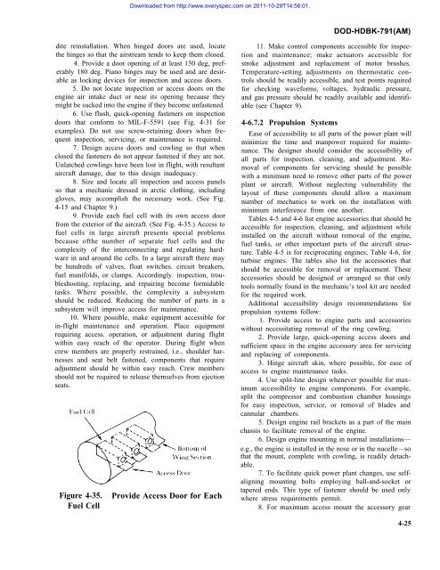
Downloaded from http://www.everyspec.<strong>com</strong> on 2011-10-29T14:56:01.DOD-HDBK-791(AM)dite reinstallation. When hinged doors are used, locatethe hinges so that the airstream tends to keep them closed.4. Provide a door opening of at least 150 deg, preferably180 deg. Piano hinges may be used and are desirableas locking devices for inspection and access doors.5. Do not locate inspection or access doors on theengine air intake duct or near its opening because theymight be sucked into the engine if they be<strong>com</strong>e unfastened.6. Use flush, quick-opening fasteners on inspectiondoors that conform to MIL-F-5591 (see Fig. 4-31 forexamples). Do not use screw-retaining doors when frequentinspection, servicing, or maintenance is required.7. Design access doors and cowling so that whenclosed the fasteners do not appear fastened if they are not.Unlatched cowlings have been lost in flight, with resultantaircraft damage, due to this design inadequacy.8. Size and locate all inspection and access panelsso that a mechanic dressed in arctic clothing, includinggloves, may ac<strong>com</strong>plish the necessary work. (See Fig.4-15 and Chapter 9.)9. Provide each fuel cell with its own access doorfrom the exterior of the aircraft. (See Fig. 4-35.) Access tofuel cells in large aircraft presents special problemsbecause ofthe number of separate fuel cells and the<strong>com</strong>plexity of the interconnecting and regulating hardwarein and around the cells. In a large aircraft there maybe hundreds of valves, float switches. circuit breakers,fuel manifolds, or clamps. Accordingly. inspection, troubleshooting,replacing, and repairing be<strong>com</strong>e formidabletasks. Where possible, the <strong>com</strong>plexity a subsystemshould be reduced. Reducing the number of parts in asubsystem will improve access for maintenance.10. Where possible, make equipment accessible forin-flight maintenance and operation. Place equipmentrequiring access. operation, or adjustment during flightwithin easy reach of the operator. During flight whencrew members are properly restrained, i.e., shoulder harnessesand seat belt fastened, <strong>com</strong>ponents that requireadjustment should be within easy reach. Crew membersshould not be required to release themselves from ejectionseats.Figure 4-35.Fuel CellProvide Access Door for Each11. Make control <strong>com</strong>ponents accessible for inspectionand maintenance; make actuators accessible forstroke adjustment and replacement of motor brushes.Temperature-setting adjustments on thermostatic controlsshould be readily accessible, and test points requiredfor checking waveforms, voltages, hydraulic pressure,and gas pressure should be readily available and identifiable(see Chapter 9).4-6.7.2 Propulsion SystemsEase of accessibility to all parts of the power plant willminimize the time and manpower required for maintenance.The designer should consider the accessibility ofall parts for inspection, cleaning, and adjustment. Removalof <strong>com</strong>ponents for servicing should be possiblewith a minimum need to remove other parts of the powerplant or aircraft. Without neglecting vulnerability thelayout of these <strong>com</strong>ponents should allow a maximumnumber of mechanics to work on the installation withminimum interference from one another.Tables 4-5 and 4-6 list engine accessories that should beaccessible for inspection, cleaning, and adjustment whileinstalled on the aircraft without removal of the engine,fuel tanks, or other important parts of the aircraft structure.Table 4-5 is for reciprocating engines; Table 4-6, forturbine engines. The tables also list the accessories thatshould be accessible for removal or replacement. Theseaccessories should be designed or arranged so that onlytools normally found in the mechanic’s tool kit are neededfor the required work.Additional accessibility design re<strong>com</strong>mendations forpropulsion systems follow:1. Provide access to engine parts and accessorieswithout necessitating removal of the ring cowling.2. Provide large, quick-opening access doors andsufficient space in the engine accessory area for servicingand replacing of <strong>com</strong>ponents.3. Hinge aircraft skin, where possible, for ease ofaccess to engine maintenance tasks.4. Use split-line design whenever possible for maximumaccessibility to engine <strong>com</strong>ponents. For example,split the <strong>com</strong>pressor and <strong>com</strong>bustion chamber housingsfor easy inspection, service, or removal of blades andcannular chambers.5. Design engine rail brackets as a part of the mainchassis to facilitate removal of the engine.6. Design engine mounting in normal installations—e.g., the engine is installed in the nose or in the nacelle—sothat the mount, <strong>com</strong>plete with cowling, is readily detachable.7. To facilitate quick power plant changes, use selfaligningmounting bolts employing ball-and-socket ortapered ends. This type of fastener should be used onlywhere stress requirements permit.8. For maximum access mount the accessory gear4-25


