

MAINTAINABILITY DESIGN TECHNIQUES METRIC - AcqNotes.com
MAINTAINABILITY DESIGN TECHNIQUES METRIC - AcqNotes.com
MAINTAINABILITY DESIGN TECHNIQUES METRIC - AcqNotes.com

Create successful ePaper yourself
Turn your PDF publications into a flip-book with our unique Google optimized e-Paper software.
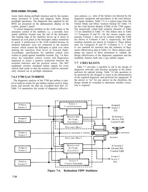
Downloaded from http://www.everyspec.<strong>com</strong> on 2011-10-29T14:56:01.DOD-HDBK-791(AM)locate faults during preflight checkout and by the maintenancepersonnel to locate and diagnose faults duringpostflight operations. The diagnostic data supplied by theBITE are presented on the alphanumeric display on thecopilot, gunner’s panel.A critical diagnostic problem on the AAH relates to theautomatic control of the stabilitor, i.e., a movable, horizontalstabilizer located near the tail of the helicopter.The leading edge of the stabilitor moves up or down tomaintain an even pitch as the helicopter makes transitionsin speed. A predecessor to the AAH crashed because itsairspeed indicators were not connected to the positionsensors, which caused the helicopter to pitch over whenmaking the transition from hover to forward flight.Accordingly, specifications for stabilitor control werewritten to guard against instability hazards. Fig. 7-6 illustratesthe redundant control system and diagnosticsemployed to insure a positive connection between theairspeed indicator and the position sensor. The BITequipment circuitry simulated failure signals for everycritical fault mode so that the monitor could be automaticallychecked out in preflight simulation.7-6.3 T700 GAS TURBINEThe diagnostic analysis of the T700 gas turbine is typicalof analysis results for gas turbine engines used in Armytrucks and aircraft; the data are excerpted from Ref. 23.Table 7-4 summarizes the results of diagnostic effectivenessanalysis, i.e.. ratio of the failures not detected by thediagnostic equipment and procedures to the total failures,for engine modules. Table 7-5 is a typical page from theFailure Mode and Effect Analysis backup for Table 7-4for the Cold Section Module (CSM) of the T700 engine.The numerically coded fault isolation elements of Table7-5 are identified in Table 7-6. The failure rates in Table7-5 Categories II and IV—for the various engine <strong>com</strong>ponents,Column 1, that can be isolated within the CSMare shown in Columns 4 and 5, respectively; the faultisolation elements are shown in Column 6. These failurerates for Categories II and IV—Columns 4, 5, 7, and8—are summed for insertion into the summary of diagnosticeffectiveness data in Table 7-4. These analysis samplingsare typical of those performed to validate thedesign effectiveness of the diagnostic equipment and thetestability features built into a gas turbine engine.7-7 CHECKLISTSTable 7-7 provides a checklist to aid in the design ofdiagnostic networks and function grouping in the primeend-item for optimal testing. Table 7-8 lists questions tobe answered by the designer to assist in the determinationof the required diagnostic and preferred test equipment. Ifthe answer is “no" for any answer on the checklists, thedesign should be restudied to determine whether correctionis required.Figure 7-6.Redundant FBW Stabilator7-20


