

MAINTAINABILITY DESIGN TECHNIQUES METRIC - AcqNotes.com
MAINTAINABILITY DESIGN TECHNIQUES METRIC - AcqNotes.com
MAINTAINABILITY DESIGN TECHNIQUES METRIC - AcqNotes.com

You also want an ePaper? Increase the reach of your titles
YUMPU automatically turns print PDFs into web optimized ePapers that Google loves.
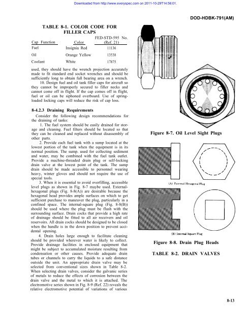
Downloaded from http://www.everyspec.<strong>com</strong> on 2011-10-29T14:56:01.DOD-HDBK-791(AM)TABLE 8-1. COLOR CODE FORFILLER CAPSFED-STD-595 No.Cap Function Color (Ref. 21)Fuel Insignia Red 11136Oil Orange Yellow 13538Coolant White 17875used, they should have the wrench projection accuratelymade to fit standard end socket wrenches and should besufficiently long to obtain full bearing area on a wrench.10. Design fuel and oil tank filler caps for aircraft sothey cannot be improperly secured to filler necks andcannot <strong>com</strong>e off in flight. If the cap <strong>com</strong>es off in flight,fuel or oil can be siphoned overboard. Use of springloadedlocking caps will reduce the risk of cap loss.8-4.2.3 Draining RequirementsConsider the following design re<strong>com</strong>mendations forthe draining of tanks:1. The fuel system should be easily drained for storageand cleaning. Fuel filters should be located so thatthey can be cleaned and replaced without disassembly ofother parts.2. Provide each fuel tank with a sump located at thelowest portion of the tank when the equipment is in itsnormal position. The sump. used for collecting sedimentand water, may be <strong>com</strong>bined with the fuel tank outlet.Provide a machine-threaded drain plug or self-lockingdrain valve at the lowest point of the tank. The sumpdrain should be made accessible to personnel wearingheavy, winter gloves and should not require the use ofspecial tools.3. When it is essential to avoid overfilling, accessiblelevel plugs as shown in Fig. 8-7 maybe used. Externalhexagonalplugs (Fig. 8-8(A)) are desirable because thehexagonal head provides ample surfaces on which to getsufficient purchase to maneuver the plug, particularly in aconfined space. The internal-square plug (Fig. 8-8(B))should be used where the plug must be flush with thesurrounding surface. Drain cocks that provide a high rateof drainage should be fitted to all air receivers and oilreservoirs. All drain cocks should be designed to be closedwhen the handle is in the down position to prevent accidentalopening.4. Drain holes large enough to facilitate cleaningshould be provided wherever water is likely to collect.Provide drainage facilities in enclosed equipment thatmight be subject to accumulated moisture resulting fromcondensation or other causes. Provide adequate draintubes or channels to carry the liquids to a safe distanceoutside the unit. An appropriate drain valve may beselected from conventional sizes shown in Table 8-2.When selecting drain valves, consider the galvanic seriesof metals to reduce the effects of corrosion between thedrain valve and the metal to which it is attached. Theelectromotive series shown in Fig. 8-9 (Ref. 22) reveals therelative electromotive potential of variations of variousFigure 8-7. Oil Level Sight PlugsFigure 8-8. Drain Plug HeadsTABLE 8-2. DRAIN VALVES8-13


