

MAINTAINABILITY DESIGN TECHNIQUES METRIC - AcqNotes.com
MAINTAINABILITY DESIGN TECHNIQUES METRIC - AcqNotes.com
MAINTAINABILITY DESIGN TECHNIQUES METRIC - AcqNotes.com

You also want an ePaper? Increase the reach of your titles
YUMPU automatically turns print PDFs into web optimized ePapers that Google loves.
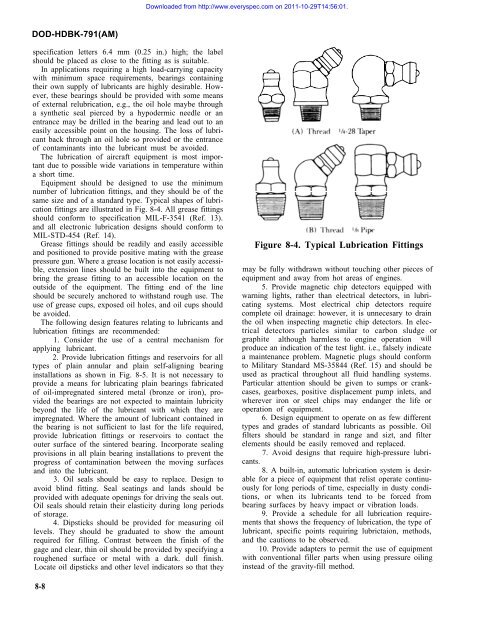
Downloaded from http://www.everyspec.<strong>com</strong> on 2011-10-29T14:56:01.DOD-HDBK-791(AM)specification letters 6.4 mm (0.25 in.) high; the labelshould be placed as close to the fitting as is suitable.In applications requiring a high load-carrying capacitywith minimum space requirements, bearings containingtheir own supply of lubricants are highly desirable. However,these bearings should be provided with some meansof external relubrication, e.g., the oil hole maybe througha synthetic seal pierced by a hypodermic needle or anentrance may be drilled in the bearing and lead out to aneasily accessible point on the housing. The loss of lubricantback through an oil hole so provided or the entranceof contaminants into the lubricant must be avoided.The lubrication of aircraft equipment is most importantdue to possible wide variations in temperature withina short time.Equipment should be designed to use the minimumnumber of lubrication fittings, and they should be of thesame size and of a standard type. Typical shapes of lubricationfittings are illustrated in Fig. 8-4. All grease fittingsshould conform to specification MIL-F-3541 (Ref. 13).and all electronic lubrication designs should conform toMIL-STD-454 (Ref. 14).Grease fittings should be readily and easily accessibleand positioned to provide positive mating with the greasepressure gun. Where a grease location is not easily accessible,extension lines should be built into the equipment tobring the grease fitting to an accessible location on theoutside of the equipment. The fitting end of the lineshould be securely anchored to withstand rough use. Theuse of grease cups, exposed oil holes, and oil cups shouldbe avoided.The following design features relating to lubricants andlubrication fittings are re<strong>com</strong>mended:1. Consider the use of a central mechanism forapplying lubricant.2. Provide lubrication fittings and reservoirs for alltypes of plain annular and plain self-aligning bearinginstallations as shown in Fig. 8-5. It is not necessary toprovide a means for lubricating plain bearings fabricatedof oil-impregnated sintered metal (bronze or iron), providedthe bearings are not expected to maintain lubricitybeyond the life of the lubricant with which they areimpregnated. Where the amount of lubricant contained inthe bearing is not sufficient to last for the life required,provide lubrication fittings or reservoirs to contact theouter surface of the sintered bearing. Incorporate sealingprovisions in all plain bearing installations to prevent theprogress of contamination between the moving surfacesand into the lubricant.3. Oil seals should be easy to replace. Design toavoid blind fitting. Seal seatings and lands should beprovided with adequate openings for driving the seals out.Oil seals should retain their elasticity during long periodsof storage.4. Dipsticks should be provided for measuring oillevels. They should be graduated to show the amountrequired for filling. Contrast between the finish of thegage and clear, thin oil should be provided by specifying aroughened surface or metal with a dark. dull finish.Locate oil dipsticks and other level indicators so that theyFigure 8-4. Typical Lubrication Fittingsmay be fully withdrawn without touching other pieces ofequipment and away from hot areas of engines.5. Provide magnetic chip detectors equipped withwarning lights, rather than electrical detectors, in lubricatingsystems. Most electrical chip detectors require<strong>com</strong>plete oil drainage: however, it is unnecesary to drainthe oil when inspecting magnetic chip detectors. In electricaldetectors particles similar to carbon sludge orgraphite although harmless to engine operation willproduce an indication of the test light. i.e., falsely indicatea maintenance problem. Magnetic plugs should conformto Military Standard MS-35844 (Ref. 15) and should beused as practical throughout all fluid handling systems.Particular attention should be given to sumps or crankcases,gearboxes, positive displacement pump inlets, andwherever iron or steel chips may endanger the life oroperation of equipment.6. Design equipment to operate on as few differenttypes and grades of standard lubricants as possible. Oilfilters should be standard in range and sizt, and filterelements should be easily removed and replaced.7. Avoid designs that require high-pressure lubricants.8. A built-in, automatic lubrication system is desirablefor a piece of equipment that relist operate continuouslyfor long periods of time, especially in dusty conditions,or when its lubricants tend to be forced frombearing surfaces by heavy impact or vibration loads.9. Provide a schedule for all lubrication requirementsthat shows the frequency of lubrication, the type oflubricant, specific points requiring lubrictaion, methods,and the cautions to be observed.10. Provide adapters to permit the use of equipmentwith conventional filler parts when using pressure oilinginstead of the gravity-fill method.8-8


