

MAINTAINABILITY DESIGN TECHNIQUES METRIC - AcqNotes.com
MAINTAINABILITY DESIGN TECHNIQUES METRIC - AcqNotes.com
MAINTAINABILITY DESIGN TECHNIQUES METRIC - AcqNotes.com

Create successful ePaper yourself
Turn your PDF publications into a flip-book with our unique Google optimized e-Paper software.
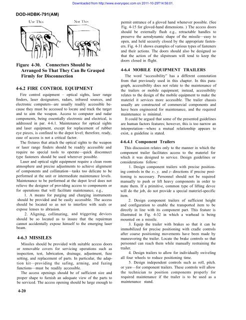
Downloaded from http://www.everyspec.<strong>com</strong> on 2011-10-29T14:56:01.DOD-HDBK-791(AM)Figure 4-30. Connectors Should beArranged So That They Can Be GraspedFirmly for Disconnection4-6.2 FIRE CONTROL EQUIPMENTFire control equipment – optical sights, laser rangefinders, laser designators, radars, infrared sources, andelectronic <strong>com</strong>puters-–are usually readily accessible becausethey must be accessed to locate and track the targetand to aim the weapon. Access to <strong>com</strong>puter and radar<strong>com</strong>ponents, being essentially electronic and electrical, isaddressed in par. 4-6.1. Maintenance for optical sightsand laser equipment, except for replacement of rubbereye pieces, is confined to the depot level; therefore, ready,ease of access is not a critical factor.The fixtures that attach the optical sights to the weaponor laser range finders should be readily accessible andrequire no special tools to operate—quick disconnecttype fasteners should be used wherever possible.Laser and optical sight equipment require a clean roomatmosphere and precise adjustments to achieve alignmentof <strong>com</strong>ponents and collimation—tasks too delicate to beperformed at the unit or intermediate maintenance levels.Maintenance to be performed at the depot level does notrelieve the designer of providing access to <strong>com</strong>ponents orfor operations that will facilitate maintenance, e.g.,1. A means for purging and charging instrumentsshould be provided and be easily accessible. The accessshould be located so as not to interfere with seals orexpose lenses to abrasion.2. Aligning, collimating, and triggering devicesshould be so located as to insure that the repairmancannot accidentally expose himself to the emerging laserbeam.4-6.3 MISSILESMissiles should be provided with suitable access doorsor removable covers for servicing operations such asinspection, test, lubrication, drainage, adjustment, fuzesetting, and replacement of parts. In particular, the adaptionkit—providing the safing, arming, and fuzingfunctions—must be readily accessible.The access openings should be of sufficient size andproper shape to furnish an adequate view of the parts tobe serviced. The access opening should be large enough topermit entrance of a gloved hand whenever possible. (SeeFig. 4-15 for gloved-hand dimensions. ) The access doorsshould be externally flush e.g., retractable handles topreserve the aerodynamic shape of the missile—easy toopen, and held securely closed by the appropriate fasteners.Fig. 4-31 shows examples of various types of fastenersand their actions. The doors should also be designed sothat the action of the slipstream will tend to keep thedoors closed in flight.4-6.4 MOBILE EQUIPMENT TRAILERSThe word “accessibility” has a different connotationfrom that previously used in this chapter. In this paragraph,accessibility does not relate to the maintenance ofthe trailers or mobile equipment; instead, accessibilityrelates to the design of the mobile equipment to make themateriel it services more accessible. The trailer chassisusually are constructed of <strong>com</strong>mercial <strong>com</strong>ponents andhave been engineered for maintenance, and the requiredmaintenance is minimal.It could be argued that some of the presented guidelinesare human factors features; however, this is too narrow aninterpretation—where a mutual relationship appears toexist, a guideline is stated.4-6.4.1 Component TrailersThis discussion relates only to the manner in which the<strong>com</strong>ponent trailer facilitates access to the materiel forwhich it was designed to service. Design guidelines orconsiderations follow:1. Design <strong>com</strong>ponent trailers with precise positioningcontrols in the x-, y, and z- directions if precise positioningis necessary. Personnel should not be requiredmanually to push or lift heavy <strong>com</strong>ponents in order tomate them. If a primitive, <strong>com</strong>mon type of lifting devcewill do the job, do not provide a special materiel-specificitem.2. Design <strong>com</strong>ponent trailers of sufficient heightand configuration to enable the transported item to bedirectly in line with its <strong>com</strong>ponent part. This feature isillustrated in Fig. 4-32 in which a warhead is beingmounted on a missile.3. Equip the trailer with brakes so that it can beimmobilized for precise positioning with cradle controlsafter coarse positioning movements have been made bymaneuvering the trailer. Locate the brake controls so thatpersonnel can reach them while manually restraining thetrailer.4. Design trailers to allow for individually swivelingall four wheels to reduce positioning time.5. Design independent controls such as roll, pitch.or yaw—for <strong>com</strong>ponent trailers. These controls will allowthe technician to position <strong>com</strong>ponents properly forrequired maintenance if the trailer is to be used as amaintenance stand.4-20


