Downloaded from http://www.everyspec.<strong>com</strong> on 2011-10-29T14:56:01.DOD-HDBK-791(AM)It is difficult to make definite <strong>com</strong>parisons of thecorrosion-resistant properties of metals because the resistanceof each varies with the chemical environments.However, in vehicle design the metals most <strong>com</strong>monlyused for their corrosion-resistant properties are—not inorder of resistance—titanium, molybdenum alloys, stainlesssteel, pure aluminum, cadmium, chromium, zinc,nickel, tin, and copper alloys. The aluminum and magnesiumalloys are seriously degraded by corrosion andshould be avoided. The automobile manufacturers haveintroduced zinc plating—either galvanizing or electroplating—ofsteel body panels and mufflers to increase corrosionresistance.Dissimilar metals that are far apart in the galvanicseries—see Fig. 8-8 and Table 8-3—-should not be directlyjoined together, but if they must be used together, theirjoining surfaces should be separated by an insulatingmaterial or both surfaces must be covered with the sameprotective coating.For more detailed coverage of corrosion and the corrosionprotection of metals, see MIL-E-5400 (Ref. 25) andRefs. 26, 27, 28, and 29 for listings of acceptablecorrosion-resistant materials.8-4.4 MOISTURE PROTECTIONThe exclusion of moisture from equipment. particularlyin the tropics, considerably eases maintenance problems.To help minimize the effects of moisture on insulatingand other materials, the guidelines that follow shouldbe considered:1. Choose materials with low moisture absorptionqualities.2. Use hermetic sealing whenever possible.3. Use gaskets and other sealing devices to keepmoisture out.4. Impregnate or encapsulate materials with fungousresistanthydrocarbon waxes and varnishes.5. Do not place bare metal parts in contact withmaterials that have been waterproofed; metal may supportfungous growth and deposit corrosive waste productson the treated material.6. When waterproofed materials are used, be surethey do not contribute to corrosion or alter electrical orphysical properties.If these methods are not practical, drain holes shouldbe provided, and chassis and racks should be channeled toprevent moisture traps. Additional information on moistureprotection can be supplied by the Prevention ofDeterioration Center, National Research Council, 2101Constitution Avenue, Washington, DC 20037. Refer alsoto MIL-E-5400 (Ref. 25) for listings of acceptablemoisture-resistant materials.8-4.5 ADJUSTMENT AND ALIGNMENTAlthough many types of equipment may require adjustmentand alignment during their useful life, tank automotiveequipment and aircraft are the most affected by thisrequirement. Items that require adjustments include tanktreads, engine timing (gasoline engines), alternator beltdrives, and cam drive belts. Aligning applies to steeringand headlights on automotive equipment and to firingcontrols and sights on guns. Some alignment and adjustmentrequirements are associated with initial installation;however, because many <strong>com</strong>ponents have a long, usefullife before wear-out, periodic inspections and adjustmentsare necessary to assure proper functioning. Whenmechanical <strong>com</strong>ponents have actuating linkages, e.g.,throttle controls and flight controls on aircraft, the controlat the <strong>com</strong>ponent and the <strong>com</strong>ponent itself shouldincorporate alignment positioning pins to assist in therapid attachment and proper positioning of the controlwithout two-person cooperation.Equipment should redesigned to require the minimumnumber of periodic maintenance adjustments. However,maintenance adjustments that cannot feasibly be eliminatedshould be simplified enough to permit theirac<strong>com</strong>plishment at the lowest practicable maintenancelevel. The use of built-in, self-adjusting devices should beconsidered provided their addition does not present amaintenance burden more difficult than manual adjustment.If adjustments are to be made manually. insure thatdisassembly of the <strong>com</strong>ponents is not required for theirac<strong>com</strong>plishment. Wherever practicable, the effect ofmanipulating the service adjustments should be clearlyand easily discernible by reference to appropriatc gages orother displays. Avoid critical adjustments, i.e., a slightmanipulation of the device (or slight variation duringnormal operation) that will cause a very large change ofthe affected parameter. Adjustment devices should havean adequate range of adjustment without being undulycritical or dependent on other adjustments. Maladjustmentsthat may occur during a servicing procedure shouldnot result in damage to any parts when the equipment isoperated under the maladjusted conditions for a period ofup to 5 min. In general, the range of control of serviceadjustments should be such as to prevent damage bymaladjustment.Alignment and adjustment devices should be neither sofine that a number of turns is required to obtain a peakvalue nor so coarse that a peak is quickly passed, whichwould necessitate delicate adjustment. Part selection andsystem design should provide a straightforward alignmentprocedure. It should be unnecessary to go back toreadjust or realign earlier stages after alignments oradjustments are made to later stages. Also it should bepossible to make all alignment adjustments without removalof any case, cover, or shield that would affect theaccuracy of alignment upon replacement. and no specialtools should be required for alignment or adjustment.Alignment and adjustment devices should be located sothey can be readily operated while the technician isobserving the displays associated with the function beingadjusted. It should be possible to check and adjust eachunit of system separately and then connect the units intoa total, functioning sytem with little or no additionaladjustment required.Components should be designed with the minimumnumber of pivots and bearing surfaces that wear and8-16
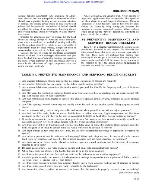
Downloaded from http://www.everyspec.<strong>com</strong> on 2011-10-29T14:56:01.DOD-HDBK-791(AM)require periodic adjustment. Any alignment or adjustmentdevices that are susceptible to vibration or shockshould have a positive locking device to assure retentionof settings. The locking device should be easy to apply andrelease, and the application and release of the lock shouldnot affect the setting of the adjustment. Traveling clampsand locking devices should be designed to avoid inadvertentrelease.Spindles for adjustments may be slotted, but the headshould be strong enough to withstand many manipulationswith a screwdriver. A method of locating and holdingthe adjusting screwdriver while in use is desirable. Ifadjustments must be made blindly, design the head toac<strong>com</strong>modate a wrench to facilitate adjustment.Consider the use of locked-nut-and-thread adjustmentsinstead of shims. Avoid shim-type adjustments that performthe dual function of adjusting bearings and positioningunits. Where corrosion of nuts and threads may be afactor in the adjustment of large <strong>com</strong>ponents, use corrosion-resistantmaterials.Where applicable, use variable pitch, V-belt drivers forhigh-speed applications. Use spring-loaded idler sprocketson chain drives to avoid frequent adjustments. Eliminateadjustment of hose fasteners used in low-pressure applications(air ducts) by using spring-type fasteners thatmaintain a constant peripheral pressure. When enclosedchain drives require periodic adjustment, automatic adjustersshould be provided.8-5 PREVENTIVE MAINTENANCE ANDSERVICING <strong>DESIGN</strong> CHECKLISTTable 8-4 is a checklist summarizing the design re<strong>com</strong>mendationspresented in this chapter. The checklist containsseveral items that were not discussed separately inthe text. These items are included here because theirnecessity in the design is so obvious that they might beinadvertently overlooked. If the answer to any question inthe checklist is “no”, the design should be restudied toascertain the need for correction.1.2.3.4.5.6.7.8.9.10.11.12.13.14.15.16.17.18.19.20.TABLE 8-4. PREVENTIVE MAINTENANCE AND SERVICING <strong>DESIGN</strong> CHECKLISTAre standard lubrication fittings used so that no special extensions or fittings are required?Are standard lubricants that are already in the federal supply system specified?Are adequate lubrication instructions (lubrication orders) provided that identify the frequency and type of lubricantsrequired?Are filler areas for <strong>com</strong>bustible materials located away from sources of heat or sparking, and are spark-resistant fillercaps and nozzles used on such equipment?Are fluid-replenishing points located so there is little chance of spillage during servicing, especially on easily damagedequipment?Are filler openings located where they are readily accessible and do not require special filling adapters or workstands?Are air reservoir safety valves easily accessible and located where pop-off action will not injure personnel?Are fuel tank filler necks, brake air cocks, flexible lines or cables, pipe runs, fragile <strong>com</strong>ponents, and like itemspositioned so they are not likely to be used as convenient footholds or handholds, thereby sustaining damage?If bleeds are required to remove entrapped air or gases from a fluid system, are they located in an easily operable andaccessible position? Are bleed valves labeled with the proper operating instructions?Are drains provided on all fluid tanks and systems, fluid-filled cases or pans, filter systems, float chambers, and otheritems designed to or likely to contain fluid that would otherwise be difficult to remove?Are drain fittings of few types and sizes used, and are they standardized according to application throughout thesystem?Are valves or petcocks used in preference to drain plugs? Where drain plugs are used, do they require only <strong>com</strong>monhand tools for operation, and does the design insure adequate tool and work clearance for operation?Are drain cocks or valves clearly labeled to indicate open and closed positions and the direction of movementrequired to open them?Do drain cocks always close with clockwise motion and open with counterclockwise motion?When drain cocks are closed, is the handle designed to be in the down position?Are drain points placed so that fluid will not drain on the technician or on sensitive equipment?Are drain points located at the lowest point when <strong>com</strong>plete drainage is required or when separation of fluids is desired(as when water is drained out of fuel tanks)?Are drain points located to permit fluid drainage directly into a waste container without use of adapters or piping?Are drain points placed where they are readily operable by the technician?Are instruction plates provided as necessary to insure that the system is properly prepared prior to draining?(cont’d on next page)8-17


