

MAINTAINABILITY DESIGN TECHNIQUES METRIC - AcqNotes.com
MAINTAINABILITY DESIGN TECHNIQUES METRIC - AcqNotes.com
MAINTAINABILITY DESIGN TECHNIQUES METRIC - AcqNotes.com

You also want an ePaper? Increase the reach of your titles
YUMPU automatically turns print PDFs into web optimized ePapers that Google loves.
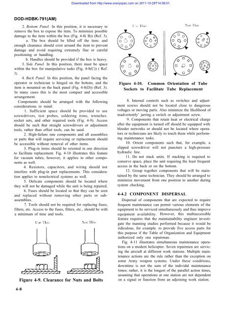
Downloaded from http://www.everyspec.<strong>com</strong> on 2011-10-29T14:56:01.DOD-HDBK-791(AM)2. Bottom Panel. In this position, it is necessary toremove the box to expose the item. To minimize possibledamage to the item within the box (Fig. 4-8( B)) (Ref. 3).a. The box should be lifted off the item. andenough clearance should exist around the item to preventdamage and avoid requiring extremely fine or carefulpositioning or handling.b. Handles should be provided if the box is heavy.3. Side Panel. In this position, there must be spacewithin the box for manipulative tasks (Fig. 4-8(C)) ( Ref.3).4. Back Panel. In this position, the panel facing theoperator or technician is hinged on the bottom, and theitem is mounted on the back panel (Fig. 4-8(D)) (Ref. 3).In many cases this is the most <strong>com</strong>pact and accessiblearrangement.Components should be arranged with the followingconsiderations in mind:1. Sufficient space should be provided to usescrewdrivers, test probes, soldering irons, wrenches.socket sets, and other required tools (Fig. 4-9). Accessshould be such that straight screwdrivers or adjustmenttools, rather than offset tools, can be used.2. High-failure rate <strong>com</strong>ponents and all assembliesor parts that will require servicing or replacement shouldbe accessible without removal of other items.3. Plug-in items should be oriented in one directionto facilitate replacement. Fig. 4-10 illustrates this featurefor vacuum tubes; however, it applies to other <strong>com</strong>ponentsas well.4. Resistors, capacitors, and wiring should notinterfere with plug-in part replacements. This considerationapplies to nonelectrical systems as well.5. Delicate <strong>com</strong>ponents should be located wherethey will not be damaged while the unit is being repaired.6. Fuses should be located so that they can be seenand replaced without removing other parts or subassemblies.7. Tools should not be required for replacing fuses,filters, etc. Access to the fuses, filters, etc., should be witha minimum of time and tools.Figure 4-9. Clearance for Nuts and BoltsFigure 4-10. Common Orientation of TubeSockets to Facilitate Tube Replacement8. Internal controls such as switches and adjustmentscrews should not be located close to dangerousvoltages or moving parts. Also minimize the likelihood ofinadvertently’ jarring a switch or adjustment screw.9. Components that retain heat or electrical chargeafter the equipment is turned off should be equipped withbleeder networks or should not be located where operatorsor technicians are likely to touch them while performingmaintenance tasks.10. Orient <strong>com</strong>ponents such that, for example, aslipped screwdriver will not puncture a high-pressurehydraulic line.11. Do not stack units. If stacking is required toconserve space, place the unit requiring the least frequentaccess in the back or on the bottom.12. Group together <strong>com</strong>ponents that will be maintainedby the same technician. They should be arranged tominimize movement from one position to another duringsystem checking.4-4.2 COMPONENT DISPERSALDispersal of <strong>com</strong>ponents that are expected to requirefrequent maintenance can permit various elements of theequipment to be serviced simultaneously and thus improveequipment availability. However, this multiaccessiblefeature requires that the maintainability engineer investigatethe manning studies performed because it would beridiculous, for example. to provide five access parts forthis purpose if the Table of Organization and Equipmentauthorized only one repairman.Fig. 4-11 illustrates simultaneous maintenance operationson a modern helicopter. Seven repairmen are servicingthe aircraft at different work stations. Multiple maintenanceactions are the rule rather than the exception onsome Army weapon systems. Under these conditions,downtime is not the sum of the individal maintenancetimes; rather, it is the longest of the parallel action times,assuming that operations at one station are not dependenton a signal or function from an adjoining work station.4-8


