

MAINTAINABILITY DESIGN TECHNIQUES METRIC - AcqNotes.com
MAINTAINABILITY DESIGN TECHNIQUES METRIC - AcqNotes.com
MAINTAINABILITY DESIGN TECHNIQUES METRIC - AcqNotes.com

You also want an ePaper? Increase the reach of your titles
YUMPU automatically turns print PDFs into web optimized ePapers that Google loves.
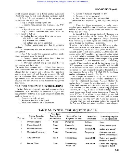
Downloaded from http://www.everyspec.<strong>com</strong> on 2011-10-29T14:56:01.DOD-HDBK-791(AM)point selection process for a liquid coolant subsystem.Apply the guide for test point selection previously stated:1. Step 1. Output parameters to be measured aretemperature and flow rate.2. Step 2. Output reading signals area. Specific temperatures plus tolerance, i.e., T i°C-±t i, degreesb. Specific flow rate Fi, i.e., meters per second3. Step 3. Internal functions that could cause theouput signal to fail area. Coolant loss or reduced flow rate between(1) Cabinet and radiator(2) Radiator and cabinet(3) Cabinet and power amplifierb. Coolant temperature rise due to defectiveradiatorc. Temperature rise due to defective liquid coolantcabinet.4. Step 4. To monitor the parameter and fault conditions,test points must be locateda. Between cabinet and radiator, both inflow andoutflow, for temperature and flow rateb. Between cabinet and power amplifier fortemperature and flow rate.To satisfy these locations and conditions, three temperaturetransducers and two flow rate transducers werechosen for the selected test locations. The transduceroutputs were examined and found to be <strong>com</strong>patible withthe test equipment. These points will produce stable voltageoutputs with the desired time constants to provideaccurate real-time readouts of the parameters that governthe system.7-5.6 TEST SEQUENCE CONSIDERATIONSBefore fixing the diagnostic plan and its associated testequipment, it is necessary to determine a logical testsequence to be followed in the event of system failure. Theanalysis should reveal1. Sequence or order of test2. System or function to be tested3. Prior tests required for measurement4. System or function required for test5. Parameters to be measured6. Processing required for interpretation.Approaches for implementing the diagnostic analysisare1. First. test those <strong>com</strong>ponents or units—powersupplies, power amplifiers, and high-voltage modulators—known to exhibit the highest failure rate. Table 7-2 illustratesthis procedure.2. Second, test the system function by function in asequence corresponding to the normal flow of signalsthrough the system. This approach, though frequentlytime-consuming, is more logical and consequently moreeasily learned by maintenance personnel.If testing is to be fully automatic, the difference in diagnostictime between the two approaches is negligible.The <strong>com</strong>plexity of the automatic system usually can bereduced greatly if self-isolating units, i.e., those units of asystem with a BIT capability, are scanned before initiatinga fault isolation procedure. The diagnostics associatedwith the prime system can be further simplified by grouping<strong>com</strong>ponents of like functions into a self-isolatingmodule. If the module is not of the throwaway type, theBIT equipment output must be <strong>com</strong>patible with the ATEat the intermediate or depot level for further diagnosticsand repair. The self-contained concept is illustrated in thetest sequence shown in Fig. 7-2 (Ref. 19) for the liquidcoolant subsystem depicted in Fig. 7-1.The example test sequence of Fig. 7-2 begins with adetermination of whether the coolant temperature T 1isbelow the established maximum T max, and whether thecoolant flow F 1exceeds the specified minimum value F min.When both answers are affirmative, the test equipmentwill indicate that the system is functioning properly.However, if T l> T maX, a test of the heat exchange radiatorinput temperature T 3and output temperature T 2must bemade. If T 2and T 3are within the specified range, the faultmust be in the coolant cabinet. If T 2and T 3are not withinspecified range and the flow rate F 2into the radiator isadequate, then the heat exchange radiator is suspect. Ifthe flow rate F 1into the power amplifier is not adequate,TABLE 7-2. TYPICAL TEST SEQUENCE (Ref. 19)7-13


