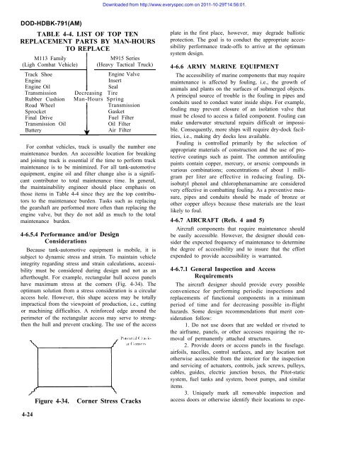
Downloaded from http://www.everyspec.<strong>com</strong> on 2011-10-29T14:56:01.DOD-HDBK-791(AM)TABLE 4-4. LIST OF TOP TENREPLACEMENT PARTS BY MAN-HOURSTO REPLACEM113 Family(Ligh Combat Vehicle)Track ShoeEngineEngine OilTransmissionRubber CushionRoad WheelSprocketFinal DriveTransmission OilBatteryM915 Series(Heavy Tactical Truck)Engine ValveInsertSealDecreasing TireMan-Hours SpringTransmissionGasketFuel FilterOil FilterAir FilterFor <strong>com</strong>bat vehicles, track is usually the number onemaintenance burden. An accessible location for breakingand joining track is essential if the time to perform trackmaintenance is to be minimized. For all tank-automotiveequipment, engine oil and filter change also is a significantcontributor to total maintenance time. In general,the maintainability engineer should place emphasis onthose items in Table 4-4 since they are the top contributorsto the maintenance burden. Tasks such as replacingthe gearshaft are performed more often than replacing theengine valve, but they do not add as much to the totalmaintenance burden.4-6.5.4 Performance and/or DesignConsiderationsBecause tank-automotive equipment is mobile, it issubject to dynamic stress and strain. To maintain vehicleintegrity regarding stress and strain calculations, accessibilitymust be considered during design and not as anafterthought. For example, rectangular hull access panelshave maximum stress at the corners (Fig. 4-34). Theoptimum solution from a stress consideration is a circularaccess hole. However, this shape access may be totallyimpractical from the viewpoint of production, i.e., cuttingor machining difficulties. A reinforced edge around theperimeter of the rectangular access may serve to strengthenthe hull and prevent cracking. The use of the accessFigure 4-34.Corner Stress Cracksplate in the first place, however, may degrade ballisticprotection. The goal is to conduct the appropriate accessibilityperformance trade-offs to arrive at the optimumsystem design.4-6.6 ARMY MARINE EQUIPMENTThe accessibility of marine <strong>com</strong>ponents that may requiremaintenance is affected by fouling, i.e., the growth ofanimals and plants on the surfaces of submerged objects.A principal source of trouble is the fouling in pipes andconduits used to conduct water inside ships. For example,fouling may prevent closure of an isolation valve thatmust be closed to access a failed <strong>com</strong>ponent. Fouling canmake underwater structural repairs difficult or impossible.Consequently, more ships will require dry-dock facilities,i.e., making dry docks less available.Fouling is controlled primarily by the selection ofappropriate materials of construction and the use of protectivecoatings such as paint. The <strong>com</strong>mon antifoulingpaints contain copper, mercury, or arsenic <strong>com</strong>pounds invarious <strong>com</strong>binations; concentrations of about 1 milligramper liter are effective in reducing fouling. Diisobutylphenol and chlorophenarsamine are consideredvery effective in <strong>com</strong>batting fouling. As a preventive measure,pipes and conduits should be made of bronze orother copper alloys because these materials are the leastlikely to foul.4-6.7 AIRCRAFT (Refs. 4 and 5)Aircraft <strong>com</strong>ponents that require maintenance shouldbe easily accessible. However, the designer should considerthe expected frequency of maintenance to determinethe degree of accessibility and to insure that the effortexpended to provide accessibility is warranted.4-6.7.1 General Inspection and AccessRequirementsThe aircraft designer should provide every possibleconvenience for performing periodic inspections andreplacements of functional <strong>com</strong>ponents in a minimumperiod of time and for decreasing possible in-flighthazards. Some design re<strong>com</strong>mendations that merit considerationfollow:1. Do not use doors that are welded or riveted tothe airframe, panels, or other accesses requiring the removalof permanently attached structures.2. Provide doors or access panels in the fuselage.airfoils, nacelles, control surfaces, and any location nototherwise accessible from the interior for the inspectionand servicing of actuators, controls, jack screws, pulleys,cables, guides, electric junction boxes, the Pitot-staticsystem, fuel tanks and system, boost pumps, and similaritems.3. Uniquely mark all removable inspection andaccess doors or otherwise identify their locations to expe-4-24
Downloaded from http://www.everyspec.<strong>com</strong> on 2011-10-29T14:56:01.DOD-HDBK-791(AM)dite reinstallation. When hinged doors are used, locatethe hinges so that the airstream tends to keep them closed.4. Provide a door opening of at least 150 deg, preferably180 deg. Piano hinges may be used and are desirableas locking devices for inspection and access doors.5. Do not locate inspection or access doors on theengine air intake duct or near its opening because theymight be sucked into the engine if they be<strong>com</strong>e unfastened.6. Use flush, quick-opening fasteners on inspectiondoors that conform to MIL-F-5591 (see Fig. 4-31 forexamples). Do not use screw-retaining doors when frequentinspection, servicing, or maintenance is required.7. Design access doors and cowling so that whenclosed the fasteners do not appear fastened if they are not.Unlatched cowlings have been lost in flight, with resultantaircraft damage, due to this design inadequacy.8. Size and locate all inspection and access panelsso that a mechanic dressed in arctic clothing, includinggloves, may ac<strong>com</strong>plish the necessary work. (See Fig.4-15 and Chapter 9.)9. Provide each fuel cell with its own access doorfrom the exterior of the aircraft. (See Fig. 4-35.) Access tofuel cells in large aircraft presents special problemsbecause ofthe number of separate fuel cells and the<strong>com</strong>plexity of the interconnecting and regulating hardwarein and around the cells. In a large aircraft there maybe hundreds of valves, float switches. circuit breakers,fuel manifolds, or clamps. Accordingly. inspection, troubleshooting,replacing, and repairing be<strong>com</strong>e formidabletasks. Where possible, the <strong>com</strong>plexity a subsystemshould be reduced. Reducing the number of parts in asubsystem will improve access for maintenance.10. Where possible, make equipment accessible forin-flight maintenance and operation. Place equipmentrequiring access. operation, or adjustment during flightwithin easy reach of the operator. During flight whencrew members are properly restrained, i.e., shoulder harnessesand seat belt fastened, <strong>com</strong>ponents that requireadjustment should be within easy reach. Crew membersshould not be required to release themselves from ejectionseats.Figure 4-35.Fuel CellProvide Access Door for Each11. Make control <strong>com</strong>ponents accessible for inspectionand maintenance; make actuators accessible forstroke adjustment and replacement of motor brushes.Temperature-setting adjustments on thermostatic controlsshould be readily accessible, and test points requiredfor checking waveforms, voltages, hydraulic pressure,and gas pressure should be readily available and identifiable(see Chapter 9).4-6.7.2 Propulsion SystemsEase of accessibility to all parts of the power plant willminimize the time and manpower required for maintenance.The designer should consider the accessibility ofall parts for inspection, cleaning, and adjustment. Removalof <strong>com</strong>ponents for servicing should be possiblewith a minimum need to remove other parts of the powerplant or aircraft. Without neglecting vulnerability thelayout of these <strong>com</strong>ponents should allow a maximumnumber of mechanics to work on the installation withminimum interference from one another.Tables 4-5 and 4-6 list engine accessories that should beaccessible for inspection, cleaning, and adjustment whileinstalled on the aircraft without removal of the engine,fuel tanks, or other important parts of the aircraft structure.Table 4-5 is for reciprocating engines; Table 4-6, forturbine engines. The tables also list the accessories thatshould be accessible for removal or replacement. Theseaccessories should be designed or arranged so that onlytools normally found in the mechanic’s tool kit are neededfor the required work.Additional accessibility design re<strong>com</strong>mendations forpropulsion systems follow:1. Provide access to engine parts and accessorieswithout necessitating removal of the ring cowling.2. Provide large, quick-opening access doors andsufficient space in the engine accessory area for servicingand replacing of <strong>com</strong>ponents.3. Hinge aircraft skin, where possible, for ease ofaccess to engine maintenance tasks.4. Use split-line design whenever possible for maximumaccessibility to engine <strong>com</strong>ponents. For example,split the <strong>com</strong>pressor and <strong>com</strong>bustion chamber housingsfor easy inspection, service, or removal of blades andcannular chambers.5. Design engine rail brackets as a part of the mainchassis to facilitate removal of the engine.6. Design engine mounting in normal installations—e.g., the engine is installed in the nose or in the nacelle—sothat the mount, <strong>com</strong>plete with cowling, is readily detachable.7. To facilitate quick power plant changes, use selfaligningmounting bolts employing ball-and-socket ortapered ends. This type of fastener should be used onlywhere stress requirements permit.8. For maximum access mount the accessory gear4-25