

MAINTAINABILITY DESIGN TECHNIQUES METRIC - AcqNotes.com
MAINTAINABILITY DESIGN TECHNIQUES METRIC - AcqNotes.com
MAINTAINABILITY DESIGN TECHNIQUES METRIC - AcqNotes.com

Create successful ePaper yourself
Turn your PDF publications into a flip-book with our unique Google optimized e-Paper software.
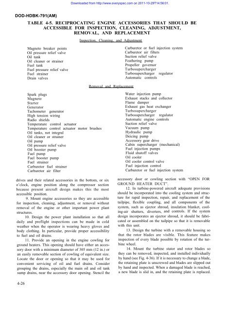
Downloaded from http://www.everyspec.<strong>com</strong> on 2011-10-29T14:56:01.DOD-HDBK-791(AM)TABLE 4-5. RECIPROCATING ENGINE ACCESSORIES THAT SHOULD BEACCESSIBLE FOR INSPECTION, CLEANING, ADJUSTMENT,REMOVAL, AND REPLACEMENTInspection, Cleaning, and AdjustmentMagneto breaker pointsOil pressure relief valveOil tankOil cleaner or strainerFuel tankFuel pressure relief valveFuel strainerDrain valvesCarburetor or fuel injection systemCarburetor air filtersSuction relief valveFeathering pumpPropeller governorTurbosuperchargerTurbosupercharger regulatorAutomatic controlsRemoval and ReplacementSpark plugsMagnetoStarterGeneratorTachometer generatorHigh tension wiringRadio shieldsTemperature control actuatorTemperature control actuator motor brushesOil tanks, not integralOil cleaner or strainerOil pumpOil pressure relief valveOil booster pumpFuel pumpFuel booster pumpFuel strainerCarburetor fuel strainerCarburetor air filterdrives and their related accessories in the bottom, or sixo’clock, engine position along the <strong>com</strong>pressor sectionbecause present aircraft design makes this the mostaccessible position.9. Mount engine accessories so they are accessiblefor inspection, cleaning, adjustment, or removal withoutremoval of the engine or other important power plantstructures.10. Design the power plant installation so that alldaily and preflight inspections can be made in coldweather when the operator is wearing heavy gloves andbody clothing. In particular, provide proper accessibilityto fuel and oil drains.11. Provide an opening in the engine cowling forground heaters. This opening should have either an accessorydoor with a minimum diameter of 305 mm (12 in.) oran easily removable section of cowling of equivalent size.Locate the door or opening so that it may be used forconvenient servicing of oil and fuel drains. Considergrouping the drains, especially the main oil and oil tanksump drains, near the accessory door opening. Stencil theWater injection pumpExhaust stacks and collectorFlame damperExhaust gas heat exchangerTurbosuperchargerTurbosupercharger regulatorAutomatic engine controlsSuction relief valveVacuum pumpHydraulic pumpDeicing pumpAccessory gear driveCabin supercharger (mechanical)Fuel injection pumpsFluid shutoff valvesOil coolerOil cooler control valveFuel injection controlCarburetor or fuel injection systemaccessory door or cowling section with “OPEN FORGROUND HEATER DUCT”.12. In turbine-powered aircraft adequate provisionsshould be incorporated into the cooling system and structurefor rapid inspection, repair, and replacement of thetailpipe, flexible coupling, and all <strong>com</strong>ponents of thesystem, such as ejector shroud, insulation blanket, cooling-airshutters, diverters, and controls. If the systemdesign incorporates an ejector shroud, it should be fabricatedor assembled on the tailpipe so that it is removablewith this unit.13. Design the turbine with a removable housing sothat the rotor blades are visible. This feature makesinspection of every blade possible by rotation of the turbinewheel.14. Mount the turbine stator and rotor blades sothey can be removed, inspected, and installed individuallyby hand (see Fig. 4-36). If it is necessary to change a blade,the retaining plate is unscrewed and blades are slipped outby hand and inspected. When a damaged blade is reached,a new blade is slid in, and the retaining plate is replaced.4-26


