MAINTAINABILITY DESIGN TECHNIQUES METRIC - AcqNotes.com
MAINTAINABILITY DESIGN TECHNIQUES METRIC - AcqNotes.com
MAINTAINABILITY DESIGN TECHNIQUES METRIC - AcqNotes.com
You also want an ePaper? Increase the reach of your titles
YUMPU automatically turns print PDFs into web optimized ePapers that Google loves.
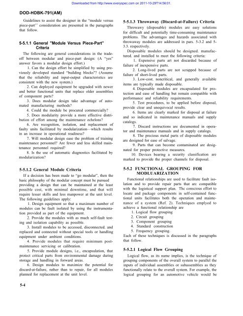
Downloaded from http://www.everyspec.<strong>com</strong> on 2011-10-29T14:56:01.DOD-HDBK-791(AM)Guidelines to assist the designer in the “module versuspiece-part’’ consideration are presented in the paragraphsthat follow.5-5.1.1 General "ModuIe Versus Piece-Part”CriteriaThe following are general considerations in the tradeoffbetween modular and piece-part design: (A “yes”answer favors a modular design effort.)1. Can the design effort be simplified by using previouslydeveloped standard “building blocks"? (Assumethat the reliability and input-output characteristics areconsistent with the new system.)2. Can deployed equipment be upgraded with newerand better functional units that replace older assembliesof <strong>com</strong>ponent parts?3. Does modular design take advantage of automatedmanufacturing methods?4. Could the module be procured <strong>com</strong>mercially?5. Does modularity provide a more effective distributionof effort among the maintenance echelons?6. Are recognition, isolation, and replacement offaulty units facilitated by modularization—which resultsin an increase in operational readiness?7. Will modular design ease the problem of trainingmaintenance personnel? Are fewer and less skilled maintenancepersonnel required?8. Is the use of automatic diagnostics facilitated bymodularization?5-5.1.2 General Module CriteriaIf a decision has been made to “go modular”, then thebasic philosophy of the modular concept must be pursuedproviding a design that can be maintained at the leastpossible cost, with minimal downtime, and that willrequire lesser skills and less manpower at the unit level.The following guidelines apply:1. Design equipment so that a maximum number ofmodules can be fault isolated by using the instrumentationprovided as part of the equipment.2. Provide the modules with as much self-fault testingand isolation capability as possible.3. Install modules to be accessed, disconnected. andreplaced and connected without special tools or handlingequipment under ambient conditions.4. Provide modules that require minimum postmaintenanceservicing or calibration.5. Provide module designs, i.e., encapsulation, thatprotect critical parts from environmental damage duringstorage and handling in forward areas.6. Design modules to maximize the potential fordiscard-at-failure, rather than to repair, for all modulesplanned for replacement at the unit level.5-5.1.3 Throwaway (Discard-at-Failure) CriteriaThrowawy (disposable) modules are easy solutionsfor difficult and potentially time-consuming maintenanceproblems. The advantages and hazards associated withthrowaway modules are addressed in pars. 5-3.2 and 5-3.3. respectively.Disposable modules should be designed. manufactured.and installed to meet the following criteria:1. Expensive parts art not discarded because offailure of inexpensive parts.2. Long-lived parts are not scrapped because offailure of short-lived parts.3. Low-cost. noncritical, and generally availableitems are typically made disposable.4. Disposable modules are encapsulated for protectionand ease of handling but remain <strong>com</strong>patible withperformance and reliability requirements.5. Test procedures, to be applied before disposal,provide clear and unequivocal results.6. Items are clearly marked for disposal at failureand so indicated in maintenance manuals and supplycatalogs.7. Discard instructions are documented in operatorand maintenance manuals and in supply catalogs.8. The precious metal parts of disposable modulesare designed for ease of salvage.9. Parts that can be<strong>com</strong>e contaminated are designatedfor proper protective measures.10. Devices bearing a security classification aremarked to provide the proper channels for disposal.5-5.2 FUNCTIONAL GROUPING FORMODLUARIZATIONFunctional relationships are used to facilitate fault isolationand to provide repair parts that arc <strong>com</strong>patiblewith the logistical support plan. Thc conscious effort tolocate and package <strong>com</strong>ponents in self-contained functionalunits facilitates both the operation and maintenanceof a system (Ref. 2). Techniques emplyed toachieve a functional relationship are1. Logical flow grouping2. Circuit grouping3. Component grouping4. Standard construction5. Frequency grouping.Each of these techniques is discussed in the paragraphsthat follow.5-5.2.1 Logical Flow GroupingLogical flow, as its name implies, is the technique ofgrouping <strong>com</strong>ponents of the overall system to parallel theinputs of individual assemblies or subassemblies as theyfunctionally relate to the overall system. For example, thelogical grouping for an automotive vehicle would be5-4


