MAINTAINABILITY DESIGN TECHNIQUES METRIC - AcqNotes.com
MAINTAINABILITY DESIGN TECHNIQUES METRIC - AcqNotes.com
MAINTAINABILITY DESIGN TECHNIQUES METRIC - AcqNotes.com
Create successful ePaper yourself
Turn your PDF publications into a flip-book with our unique Google optimized e-Paper software.
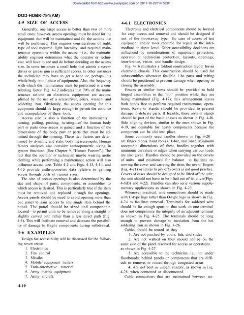
Downloaded from http://www.everyspec.<strong>com</strong> on 2011-10-29T14:56:01.DOD-HDBK-791(AM)4-5 SIZE OF ACCESSGenerally, one large access is better than two or moresmall ones; however, access openings must be sized for theequipment that will be maintained and for the actions thatwill be performed. This requires considerations of sight,type of tool required, light intensity, and required maintenanceoperations within the access—i.e., the maintainabilityengineer determines what the operator or technicianwill have to see and do before deciding on the accesssize. In some instances a small hole that admits a screwdriveror grease gun is sufficient access. In other instancesthe technician may have to get a hand or, perhaps, hiswhole body into a piece of equipment. Also, the frequencywith which the maintenance must be performed is a contributingfactor. Fig. 4-12 indicates that 70% of the maintenanceactions on electronic equipment are ac<strong>com</strong>plishedby the use of a screwdriver, pliers, wrench, andsoldering iron. Obviously, the access opening for thisequipment should be large enough to permit the entranceand manipulation of these tools.Access size is also a function of the movementsturning, pulling, pushing, twisting—of the human bodypart or parts once access is gained and a function of thedimensions of the body part or parts that must be admittedthrough the opening. These two factors are determinedby dynamic and static body measurements. Humanfactors analyses also consider anthropometric sizing insystem functions. (See Chapter 9, “Human Factors”.) Thefact that the operator or technician maybe wearing arcticclothing while performing a maintenance action will alsoinfluence access size. Table 4-2 and Figs. 4-13, 4-14, and4-15 provide anthropometric data relative to gainingaccess through ports of various sizes.The size of access openings is also determined by thesize and shape of parts, <strong>com</strong>ponents, or assemblies towhich access is desired. This is particularly true if the itemmust be removed and replaced through the openings.Access panels should be sized to avoid opening more thanone panel to gain access to any single item behind thepanel. The panel should be sized and <strong>com</strong>ponentslocated—to permit units to be removed along a straight orslightly curved path rather than a less direct path (Fig.4-5). This will facilitate removal and decrease the possibilityof damage to fragile <strong>com</strong>ponents during withdrawal.4-6 EXAMPLESDesign for accessibility will be discussed for the followingseven areas:1. Electronics2. Fire control3. Missiles4. Mobile equipment trailers5. Tank-automotive materiel6. Army marine equipment7. Army aircraft.4-6.1 ELECTRONICSElectronic and electrical <strong>com</strong>ponents should be locatedfor easy access and removal and should be designed ifnot of the throwaway type for case of access of testequipment and/or tools required for repair at the intermediateor depot level. Other accessibility decisions areinfluenced by considerations of equipment protection,operator or technician protection, layouts, openings,interference, vision. and handle design.Fig. 4-16 illustrates a foldout construction layout for-anelectronic chassis. This construction should be used forsubassemblies whenever feasible. l-he parts and wiringshould be positioned to prevent damage when opening orclosing the assembly.Braces or similar items should be provided to holdhinged assemblies in the “out” position while they arebeing maintained (Fig. 4-17); this arrangement leavesboth hands free to perform required rnaintenance operations.Rests or stands should be provided to presentdamage to delicate parts. If feasible, these rests or standsshould be part of the basic chassis as shown in Fig. 4-l8.Side aligning devices, similar to the ones shown in Fig.4-19, are desirable for heavy <strong>com</strong>ponents because the<strong>com</strong>ponent can be slid into place.Some <strong>com</strong>monly used handles shown in Fig. 4-20are finger recess. hand recess. T-bar, and J-bar. Minimumacceptable dimensions of these handles together withminimum curvature or edges when carrying various loadsare also given. Handles should be provided on the coversof units and positioned for balance to facilitate removingthe cover and carrying the item; the use of fingers(Fig. 4-21) or levers to pry off covers is not good practice.Covers of cases should be designed to be lifted off the unit;the unit should not have to be lifted out of its cover(Figs.4-8(B) and 4-22). Handles can also serie various supplementaryapplications as shown in Fig. 4-23.Whenever practical, wire connections should be madewith U-type lugs rather than O-type lugs as shown in Fig.4-24 to facilitate removal. Termimals for soldered wireshould be far enough apart so that work on one terminaldoes not <strong>com</strong>promise the integrity of an adjacent terminalas shown in Fig. 4-25. The terminals should be longenough to prevent damage to insulation from the hotsoldering iron as shown in Fig. 4-26.Cables should be routed so they1. Are not pinched by doors, lids, and slides2. Are not walked on they should not be on thesame side of the panel reserved for access or operationsas shown in Fig. 4-273. Are accessible to the technician i.e., not underfloorboards, behind panels or <strong>com</strong>ponents that are difficultto remove, or routed through congested areas4. Are not bent or unbent sharply, as shown in Fig.4-28, when connected or disconnected.Cable connections that are maintained between sta-4-10


