research activities in 2007 - CSEM
research activities in 2007 - CSEM
research activities in 2007 - CSEM

You also want an ePaper? Increase the reach of your titles
YUMPU automatically turns print PDFs into web optimized ePapers that Google loves.
RISE – The Rich Sens<strong>in</strong>g Concept<br />
A. Hutter, D. Beyeler, A. Brenzikofer, E. Grenet, F. Rampogna, L. von Allmen, C. Urban, P. Nussbaum<br />
With<strong>in</strong> the RISE project a camera-based wireless sensor network for people detection and track<strong>in</strong>g purposes has been implemented. This sensor<br />
network, which is based on three vision sensors and two 3D time-of-flight cameras, is an ideal test-bed for long-term operational tests and the<br />
development of advanced algorithms. Furthermore, the <strong>in</strong>stallation is well suited for life demonstration purposes.<br />
The multi-discipl<strong>in</strong>ary project RISE targets the elaboration of a<br />
heterogeneous sensor network for the purpose of people<br />
detection and track<strong>in</strong>g with<strong>in</strong> home and build<strong>in</strong>g areas. As a<br />
result of the first project phase, which ended <strong>in</strong> <strong>2007</strong>, a<br />
demonstrator has been implemented <strong>in</strong> the <strong>CSEM</strong> entrance<br />
hall. The demonstrator is based on two different camera<br />
types: low power vision sensors [1] and 3D time-of-flight<br />
cameras [2] . Vision sensors exploit the contrast <strong>in</strong>formation of<br />
the observed scene and are dist<strong>in</strong>guished by their huge<br />
dynamic range of 100 dB as well as the low power<br />
consumption of 80 mW. 3D time-of-flight cameras, on the<br />
other hand, provide a three-dimensional representation of the<br />
observed scene. With<strong>in</strong> the RISE project the vision sensors<br />
are used to detect and track persons and objects whereas the<br />
3D time-of-flight cameras are utilized <strong>in</strong> order to provide<br />
additional height <strong>in</strong>formation of the detected objects. Further<br />
essential components of the system are the wireless<br />
communication l<strong>in</strong>k together with the data fusion entity. In this<br />
article the basic concept together with the implemented <strong>in</strong>terwork<strong>in</strong>g<br />
of the cameras and the wireless system is described.<br />
The data fusion algorithm and the related issues are subject to<br />
a separate article [3] .<br />
The demonstration test-bed covers an area of approximately<br />
150 m 2 . The vision sensors operate with a 2.6 mm fish-eye<br />
objective, which <strong>in</strong> turn provides a relatively large field of<br />
vision, e.g. the area that is observed by one particular camera.<br />
As such, the vision sensors have overlapp<strong>in</strong>g fields of vision<br />
and cover the entire entrance area rang<strong>in</strong>g from the entrance<br />
over the two entrance side areas to the reception desk. The<br />
field of vision of the 3D time-of-flight cameras, which require<br />
active illum<strong>in</strong>ation, is limited to an area with a diameter of<br />
approximately 2 meters. One 3D camera is positioned close to<br />
the entrance whereas the second 3D camera is located right<br />
<strong>in</strong> front of the reception desk. The network coord<strong>in</strong>ator, which<br />
acts as wireless data concentrator, is located <strong>in</strong> a closed box<br />
with wooden shield<strong>in</strong>g right under the central monitor <strong>in</strong> the<br />
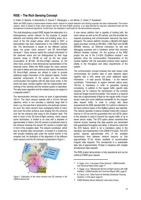
reception hall. An illustration of the disposition of the different<br />
vision sensors and the 3D cameras is presented <strong>in</strong> Figure 1.<br />
Figure 1: Disposition of the vision sensors and 3D cameras <strong>in</strong> the<br />
<strong>CSEM</strong> entrance hall<br />
A new sensor platform that is capable of host<strong>in</strong>g both, the<br />
vision sensor as well as the 3D camera, and that provides the<br />
required process<strong>in</strong>g and communication resources has been<br />
designed. The sensor platform <strong>in</strong>cludes a Blackf<strong>in</strong> 533 digital<br />
signal processor runn<strong>in</strong>g at 500 MHz, 2 MB Flash and 32 MB<br />
SDRAM memory, an Ethernet connection for test and<br />
debugg<strong>in</strong>g purposes and a hardware socket that connects<br />
different wireless modules. For the purpose of the RISE<br />
project the use of the 2.4 GHz ZorgWave module [4] was<br />
selected, s<strong>in</strong>ce the communication characteristics of the<br />
module together with the associated protocol stack respond<br />
ideally to the throughput and delay requirements of the<br />
system.<br />
The communication concept foresees that each sensor node<br />
communicates the position data of each detected object<br />
together with a time stamp and some additional object<br />
<strong>in</strong>formation – <strong>in</strong> total around 100 Bytes – to the network<br />
coord<strong>in</strong>ator. Transmission at regular <strong>in</strong>tervals (about every<br />
100 ms) is mandatory <strong>in</strong> order to guarantee track<strong>in</strong>g<br />
consistency. In addition to this regular traffic, specific data<br />
requests (as for <strong>in</strong>stance the transmission of the currently<br />
observed image) should be possible. This results <strong>in</strong> a required<br />
data rate of approximately 8 kbps for the regular traffic of each<br />
sensor node plus some additional bandwidth for the irregular<br />
data request traffic. In order to comply with these<br />
requirements the IEEE standard 802.15.4 (which is identical to<br />
the basic protocol layers of the ZigBee system) was selected.<br />
The network operates <strong>in</strong> beacon-enabled mode with a beacon<br />
<strong>in</strong>terval of 123 ms and the guaranteed time slot (GTS) option<br />
of the standard is used to transmit the regular traffic of up to<br />
seven sensor nodes. The GTS option allows contention-free<br />
channel access mean<strong>in</strong>g that data packets are transmitted<br />
with guaranteed throughput and delay. It should be noted that<br />
the GTS feature, which is not a mandatory option <strong>in</strong> the<br />
standard, was implemented <strong>in</strong> the <strong>CSEM</strong> K15 stack. The GTS<br />
portion requires approximately 44% of the available<br />
transmission time between network beacons so that<br />
approximately 67 ms rema<strong>in</strong> available to accommodate<br />
irregular data requests. This corresponds to a susta<strong>in</strong>able<br />
data rate of approximately 15 kbps <strong>in</strong> situations with multiple<br />
simultaneous data requests.<br />
The RISE project demonstrator is fully operational and can be<br />
visited at <strong>CSEM</strong> upon request.<br />
[1] S. Gyger, et al., “Low-power Vision Sensors”, <strong>CSEM</strong> Scientific<br />
and Technical Report 2004, page 17<br />
[2] T. Oggier, et al., “M<strong>in</strong>iaturized 3D time-of-flight Camera with USB<br />
Interface”, <strong>CSEM</strong> Scientific and Technical Report 2002, page 37<br />
[3] E. Franzi, et al., “Data Fusion for Wireless Distributed Track<strong>in</strong>g<br />
Systems”, <strong>in</strong> this report, page 24<br />
[4] <strong>CSEM</strong> Wireless Sensor Networks, www.csem.ch/wsn<br />
15