research activities in 2007 - CSEM
research activities in 2007 - CSEM
research activities in 2007 - CSEM

Create successful ePaper yourself
Turn your PDF publications into a flip-book with our unique Google optimized e-Paper software.
PackTime – Zero-Level Packag<strong>in</strong>g of Silicon Time-base<br />
D. Ruffieux, J. Baborowski, M. Fretz, S. Grossmann, C. Henzel<strong>in</strong>, I. Kjelberg, T.C. Le, J.-M. Mayor, A. Pezous, A.-C. Pliska,<br />
A. Schifferle, G. Sp<strong>in</strong>ola Durante, Y. Welte<br />
The development of a thermally compensated silicon time-base and the associated packag<strong>in</strong>g to yield a m<strong>in</strong>iature vacuum-sealed cavity around the<br />
resonator requires multidiscipl<strong>in</strong>ary competences <strong>in</strong> the fields of IC, MEMS design/fabrication, packag<strong>in</strong>g, f<strong>in</strong>ite element model<strong>in</strong>g and metrology.<br />
The low power frequency and tim<strong>in</strong>g market relies almost<br />
exclusively on quartz resonators to derive precise and low<br />
ag<strong>in</strong>g references thanks to the availability of crystal cuts with<br />
null first order temperature coefficient on frequency (TCF).<br />
Silicon on the other hand appears quite attractive from a<br />
m<strong>in</strong>iaturization perspective but suffers from a severe<br />
drawback with a TCF close to -30 ppm/°C whatever the<br />
crystal orientation. Consequently, electronic compensation<br />
that can possibly be comb<strong>in</strong>ed with structural<br />
compensation [1, 2] appears as one of the most promis<strong>in</strong>g<br />
workarounds to reach performances similar or better than that<br />
of AT-cut quartz crystal achiev<strong>in</strong>g null first and second TCF.<br />
The development of such a high performance, m<strong>in</strong>iature and<br />
low power real time silicon clock (RTC) together with the<br />
associated packag<strong>in</strong>g technology entails multidiscipl<strong>in</strong>ary<br />
competences <strong>in</strong> IC and MEMS design/fabrication, packag<strong>in</strong>g,<br />
FEM and metrology. The <strong>activities</strong> ongo<strong>in</strong>g <strong>in</strong> each of these<br />
fields are described <strong>in</strong> the follow<strong>in</strong>g sections after an overview<br />
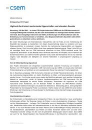
of the system is presented. Figure 1 shows a cross-section of<br />
the envisioned m<strong>in</strong>iature whole silicon time-base that consists<br />
of a rear side packaged silicon resonator <strong>in</strong>tegrated on a SOI<br />
substrate that is assembled and <strong>in</strong>terconnected by a flip-chip<br />
and reflow process to an IC capp<strong>in</strong>g die generat<strong>in</strong>g the<br />
thermally compensated clock. The reflow process is<br />
performed under vacuum and should ensure hermeticity of the<br />
cavity that is formed around the resonator to take advantage<br />
of the high quality factor of the latter and m<strong>in</strong>imize any ag<strong>in</strong>g<br />
of the time-base.<br />
Figure 1: Cross-section of the m<strong>in</strong>iature zero-level packaged silicon<br />
timebase with a vacuum-sealed cavity around the resonator<br />
A FEM CAD model of the complete resonator <strong>in</strong>clud<strong>in</strong>g its<br />
package has been developed to help determ<strong>in</strong>e the sensitive<br />
parameters that affect the resonator frequency dur<strong>in</strong>g and<br />
follow<strong>in</strong>g the assembly process and could then be responsible<br />
for excessive ag<strong>in</strong>g. Thermo-mechanical simulations are also<br />
very valuable to predict the performance of the compensated<br />
time base that relies on a good match<strong>in</strong>g of the resonator and<br />
sensor temperature and that may be affected dur<strong>in</strong>g thermal<br />
transients. The lack of availability of precise data for the<br />
stiffness of the materials <strong>in</strong>volved <strong>in</strong> the fabrication of the<br />
resonators and their temperature dependency has motivated<br />
the development of an optical metrology bank [3] and dedicated<br />
test structures that should help future resonator design and<br />
allow more precise FEM analysis once measurement and<br />
extraction is completed.<br />
16<br />
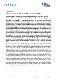
The resonator exploits a high-Q <strong>in</strong>-plane, longitud<strong>in</strong>al,<br />
extensional mode and is formed of a T-shaped silicon beam,<br />
typically 1000 x 250 µm 2 , anchored at its base end, with an<br />
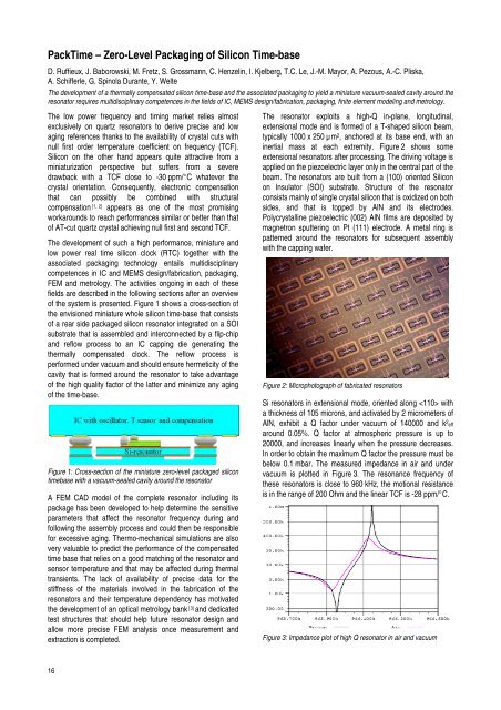
<strong>in</strong>ertial mass at each extremity. Figure 2 shows some<br />
extensional resonators after process<strong>in</strong>g. The driv<strong>in</strong>g voltage is<br />
applied on the piezoelectric layer only <strong>in</strong> the central part of the<br />
beam. The resonators are built from a (100) oriented Silicon<br />
on Insulator (SOI) substrate. Structure of the resonator<br />
consists ma<strong>in</strong>ly of s<strong>in</strong>gle crystal silicon that is oxidized on both<br />
sides, and that is topped by AlN and its electrodes.<br />
Polycrystall<strong>in</strong>e piezoelectric (002) AlN films are deposited by<br />
magnetron sputter<strong>in</strong>g on Pt (111) electrode. A metal r<strong>in</strong>g is<br />
patterned around the resonators for subsequent assembly<br />
with the capp<strong>in</strong>g wafer.<br />
Figure 2: Microphotograph of fabricated resonators<br />
Si resonators <strong>in</strong> extensional mode, oriented along with<br />
a thickness of 105 microns, and activated by 2 micrometers of<br />
AlN, exhibit a Q factor under vacuum of 140000 and k 2 eff<br />
around 0.05%. Q factor at atmospheric pressure is up to<br />
20000, and <strong>in</strong>creases l<strong>in</strong>early when the pressure decreases.<br />
In order to obta<strong>in</strong> the maximum Q factor the pressure must be<br />
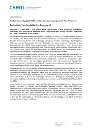
below 0.1 mbar. The measured impedance <strong>in</strong> air and under<br />
vacuum is plotted <strong>in</strong> Figure 3. The resonance frequency of<br />
these resonators is close to 960 kHz, the motional resistance<br />
is <strong>in</strong> the range of 200 Ohm and the l<strong>in</strong>ear TCF is -28 ppm/°C.<br />
Figure 3: Impedance plot of high Q resonator <strong>in</strong> air and vacuum