research activities in 2007 - CSEM
research activities in 2007 - CSEM
research activities in 2007 - CSEM

You also want an ePaper? Increase the reach of your titles
YUMPU automatically turns print PDFs into web optimized ePapers that Google loves.
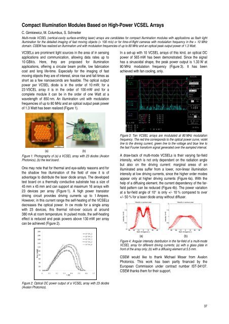
Compact Illum<strong>in</strong>ation Modules Based on High-Power VCSEL Arrays<br />
C. Gimkiewicz, M. Columbus, S. Schneiter<br />
Multi-mode VCSEL (vertical-cavity surface-emitt<strong>in</strong>g laser) arrays are candidates for compact illum<strong>in</strong>ation modules with applications as flash light<br />
illum<strong>in</strong>ation for the detailed imag<strong>in</strong>g of fast mov<strong>in</strong>g objects (> 100 m/s) or for time-of-flight cameras with modulation frequency <strong>in</strong> the > 10 MHz<br />
doma<strong>in</strong>. <strong>CSEM</strong> has realized an illum<strong>in</strong>ation unit with modulation frequencies of up to 80 MHz and an optical peak output power of 1.3 Watt.<br />
VCSELs are prom<strong>in</strong>ent light sources <strong>in</strong> the area of <strong>in</strong> sens<strong>in</strong>g<br />
applications and communication, allow<strong>in</strong>g data rates up to<br />
10 GBit/s. Here, they are proposed for illum<strong>in</strong>ation<br />
applications, offer<strong>in</strong>g a circular beam profile, low fabrication<br />
cost and long life-time. Especially for the imag<strong>in</strong>g of fast<br />
mov<strong>in</strong>g objects they are of <strong>in</strong>terest, s<strong>in</strong>ce rise and fall times as<br />
short as a few nanoseconds are feasible. The optical output<br />
power per VCSEL diode is <strong>in</strong> the order of 10 mW; for a<br />
23 VSCEL array it is <strong>in</strong> the order of 100 mW and for a<br />
complete module it can be <strong>in</strong> the order of one Watt at a<br />
wavelength of 850 nm. An illum<strong>in</strong>ation unit with modulation<br />
frequencies of up to 80 MHz and an optical output peak power<br />
of 1.3 Watt has been realized (Figure 1).<br />
(a) (b)<br />
Figure 1: Photography of (a) a VCSEL array with 23 diodes (Avalon<br />
Photonics), (b) the test board.<br />
One may note that for thermal and eye-safety reasons and for<br />
the shadow free illum<strong>in</strong>ation of the field of view it is of<br />
advantage to distribute the laser diode arrays. The developed<br />
test board on a thermally conductive substrate has a size of<br />
45 mm x 45 mm and can support at maximum 16 arrays with<br />
23 devices per array (Figure 1). A high power transistor<br />
driv<strong>in</strong>g circuit provides driv<strong>in</strong>g currents up to 1 Ampere.<br />
However, <strong>in</strong> this current range the self-heat<strong>in</strong>g of the VCSELs<br />
decreases the optical power. In cw mode for a s<strong>in</strong>gle array<br />
with 23 devices, this thermal roll-over occurs at around<br />
380 mA at room temperature. In pulsed mode, the self-heat<strong>in</strong>g<br />
effect is reduced and peak powers above 130 mW per array<br />
can be achieved (Figure 2).<br />
Figure 2: Optical DC power output of a VCSEL array with 23 diodes<br />
(Avalon Photonics).<br />
In a set-up with 10 VCSEL arrays of this k<strong>in</strong>d, an optical DC<br />
power of 565 mW has been demonstrated. S<strong>in</strong>ce the signal<br />
has a s<strong>in</strong>usoidal shape, the peak power output is 1.33 W at<br />
80 MHz modulation frequency (Figure 3). It has been<br />
achieved with fan cool<strong>in</strong>g, only.<br />
Figure 3: Ten VCSEL arrays are modulated at 80 MHz modulation<br />
frequency. The red l<strong>in</strong>e corresponds to the optical power curve, violet<br />
l<strong>in</strong>e to the driv<strong>in</strong>g current, green l<strong>in</strong>e to the voltage and blue l<strong>in</strong>e to<br />
the fast Fourier transform signal generated over the sampled <strong>in</strong>terval.<br />
A draw-back of multi-mode VCSELs is their vary<strong>in</strong>g far-field<br />
<strong>in</strong>tensity, which is not only dependent on the radiation angle<br />
but also on the driv<strong>in</strong>g current: marg<strong>in</strong>al areas of an<br />
illum<strong>in</strong>ated area suffer from a lower, non-l<strong>in</strong>ear illum<strong>in</strong>ation<br />
<strong>in</strong>tensity at low driv<strong>in</strong>g currents, s<strong>in</strong>ce the higher order modes<br />
appear only at higher driv<strong>in</strong>g currents (Figure 4a). With the<br />
help of a diffus<strong>in</strong>g element, the current dependency of the farfield<br />
pattern can be reduced (Figure 4b). The power variation<br />
at a far-field angle of 10° is only +/- 10 % compared to over<br />
+/- 50 % for a laser diode array without diffuser.<br />
(a) (b)<br />
Figure 4: Angular <strong>in</strong>tensity distribution <strong>in</strong> the far-field of a multi-mode<br />
VCSEL array for different driv<strong>in</strong>g currents; (a) with a glass plate <strong>in</strong><br />
front of the array only; (b) with a diffus<strong>in</strong>g element at 5.5 mm.<br />
<strong>CSEM</strong> would like to thank Michael Moser from Avalon<br />
Photonics. This work has been partly f<strong>in</strong>anced by the<br />
European Commission under contract number IST-34107.<br />
<strong>CSEM</strong> thanks them for their support.<br />
37