research activities in 2007 - CSEM
research activities in 2007 - CSEM
research activities in 2007 - CSEM

You also want an ePaper? Increase the reach of your titles
YUMPU automatically turns print PDFs into web optimized ePapers that Google loves.
Quasi-Harmonic Quadrature CMOS Relaxation Oscillator<br />
J. Chabloz, D. Ruffieux<br />
In this paper, a solution to realize a local oscillator (LO) for a low power super-heterodyne receiver is presented. The complete local frequency<br />
synthesis solution comprises a fixed-frequency bulk-acoustic wave (BAW) RF oscillator with low phase noise and low tun<strong>in</strong>g range.<br />
A quasi-harmonic quadrature relaxation oscillator with a large tun<strong>in</strong>g range is realized and can be used to compensate for variations <strong>in</strong> the<br />
RF oscillator as well as to cover the entire bandwidth for multiple channel selection.<br />
The receiver for which the presented oscillator is specifically<br />
designed is based on a super-heterodyne architecture and its<br />
block schematic is described <strong>in</strong> Figure 1. The receiver frontend<br />
and baseband parts have already been <strong>in</strong>tegrated and<br />
characterized with external oscillators [1] . A BAW oscillator<br />
embedded with<strong>in</strong> a digital frequency synthesis [2] is used as a<br />
first local source (BAW RF LO) and runs at a fixed frequency,<br />
determ<strong>in</strong>ed by the physical dimensions of the BAW resonator.<br />
The second downconversion uses a quadrature relaxation<br />
oscillator (IF LO) with a large tun<strong>in</strong>g range [3] that is presented<br />
below.<br />
28<br />
Passband<br />
Balun<br />
BAW<br />
Filter<br />
2400.0 - 2483.5 MHz<br />
On-chip<br />
LNA<br />
2330.0 MHz<br />
fixed<br />
BAW<br />
LO<br />
IF Amplifier<br />
Quadrature<br />
IF Oscill.<br />
Frequency Synthesis<br />
Figure 1: Super-heterodyne receiver architecture<br />
70.0 - 153.5 MHz<br />
tunable<br />
S<strong>in</strong>ce the second downconversion is direct, the selected<br />
channel frequency is determ<strong>in</strong>ed by the sum or the difference<br />
of both oscillator frequencies. Therefore the allowed frequency<br />
excursion on the second oscillator allows to compensate<br />
entirely for the lack of tunability of the first one.<br />
The proposed quasi-harmonic quadrature relaxation oscillator<br />
architecture is described <strong>in</strong> Figure 2. Coupl<strong>in</strong>g transistors are<br />
used to couple two classical relaxation oscillator cores.<br />
Coupl<strong>in</strong>g<br />
transistors<br />
M3<br />
M1<br />
M2<br />
Figure 2: Quadrature oscillator architecture<br />
The wide variation of bias current needed to tune the<br />
oscillation frequency over the required range also creates<br />
wide variations <strong>in</strong> the oscillator operat<strong>in</strong>g po<strong>in</strong>t, more<br />
specifically <strong>in</strong> the steady-state oscillation amplitude. In order<br />
to <strong>in</strong>crease the tun<strong>in</strong>g range, l<strong>in</strong>earize the current-to-frequency<br />
characteristic and allow the oscillator to stay <strong>in</strong> the quasiharmonic<br />
mode over the entire range, an amplitude control<br />
has been designed.<br />
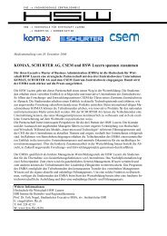
The presented circuit has been fabricated <strong>in</strong> a standard<br />
0.18 µm CMOS process. Figure 3 shows the actual receiver<br />
test chip photograph. The BAW resonator is bonded together<br />
with the chip.<br />
Figure 3: Receiver test chip photograph<br />
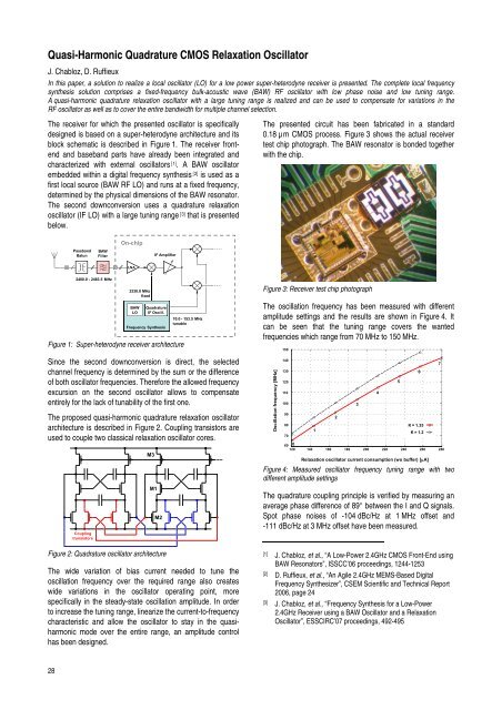
The oscillation frequency has been measured with different<br />
amplitude sett<strong>in</strong>gs and the results are shown <strong>in</strong> Figure 4. It<br />
can be seen that the tun<strong>in</strong>g range covers the wanted<br />
frequencies which range from 70 MHz to 150 MHz.<br />
Oscillation frequency [MHz]<br />
150<br />
140<br />
130<br />
120<br />
110<br />
100<br />
90<br />
80<br />
70<br />
60 0<br />
120<br />
140<br />
1<br />
160<br />
2<br />
180<br />
3<br />
200<br />
Relaxation oscillator current consumption (wo buffer) [μA]<br />
4<br />
220<br />
5<br />
240<br />
6<br />
K = 1.35<br />
K = 1.2<br />
Figure 4: Measured oscillator frequency tun<strong>in</strong>g range with two<br />
different amplitude sett<strong>in</strong>gs<br />
The quadrature coupl<strong>in</strong>g pr<strong>in</strong>ciple is verified by measur<strong>in</strong>g an<br />
average phase difference of 89° between the I and Q signals.<br />
Spot phase noises of -104 dBc/Hz at 1 MHz offset and<br />
-111 dBc/Hz at 3 MHz offset have been measured.<br />
[1] J. Chabloz, et al., “A Low-Power 2.4GHz CMOS Front-End us<strong>in</strong>g<br />
BAW Resonators”, ISSCC’06 proceed<strong>in</strong>gs, 1244-1253<br />
[2] D. Ruffieux, et al., “An Agile 2.4GHz MEMS-Based Digital<br />
Frequency Synthesizer”, <strong>CSEM</strong> Scientific and Technical Report<br />
2006, page 24<br />
[3] J. Chabloz, et al., “Frequency Synthesis for a Low-Power<br />
2.4GHz Receiver us<strong>in</strong>g a BAW Oscillator and a Relaxation<br />
Oscillator”, ESSCIRC’07 proceed<strong>in</strong>gs, 492-495<br />
260<br />
7<br />
280