research activities in 2007 - CSEM
research activities in 2007 - CSEM
research activities in 2007 - CSEM

You also want an ePaper? Increase the reach of your titles
YUMPU automatically turns print PDFs into web optimized ePapers that Google loves.
In order to optimize the performances of the resonator and<br />
guarantee long-term frequency stability, one needs to perform<br />
hermetic packag<strong>in</strong>g under reduced pressure. The rear side of<br />
the resonators is closed hermetically by low temperature<br />
fusion bond<strong>in</strong>g (with Si wafer) or by anodic bond<strong>in</strong>g (with<br />
Pyrex). Both methods require an extremely smooth surface of<br />
the wafer.<br />
The resonator chips are then vacuum encapsulated us<strong>in</strong>g<br />
silicon caps (ultimately work<strong>in</strong>g ICs) and AuSn (80% wt Au)<br />
solder<strong>in</strong>g technology. Metallic alloy materials provide both<br />
low-permeability seal<strong>in</strong>g characteristics as well as electrical<br />
conduction for the resonator driv<strong>in</strong>g <strong>in</strong>terconnects. The AuSn<br />
electroplat<strong>in</strong>g process was carried out at the Fraunhofer<br />
Institute for Reliability and Micro<strong>in</strong>tegration (IZM FhG).<br />
Vacuum seal<strong>in</strong>g of the resonator chips is done through a twostep<br />
process:<br />
• Tack<strong>in</strong>g of the seal<strong>in</strong>g cap on the resonator chip at a<br />
temperature below the AuSn melt<strong>in</strong>g po<strong>in</strong>t us<strong>in</strong>g flip-chip<br />
• Reflow under vacuum <strong>in</strong> a dedicated oven<br />
The tack<strong>in</strong>g methodology proved to be successful. Taguchi<br />
runs us<strong>in</strong>g thermo-compression parameters (temperature,<br />
force, dwell<strong>in</strong>g time) as variable experimental factors were<br />
carried out.<br />
Reflow process development, where result<strong>in</strong>g vacuum level is<br />
monitored through Q factor measurements, is on-go<strong>in</strong>g.<br />
A differential oscillator structure has been chosen to m<strong>in</strong>imize<br />
the circuit power dissipation despite the large shunt<br />
capacitance of the resonator (~10 pF). A programmable<br />
fractional divider is used to generate a thermally compensated<br />
32768 Hz clock from the 960 kHz oscillator signal that drifts by<br />
-28 ppm/°C. The output of a high resolution temperature<br />
sensor <strong>in</strong>tegrated on the same die is used by a sequencer to<br />
implement an open-loop compensation algorithm that requires<br />
<strong>in</strong>itial calibration of the resonator absolute frequency and<br />
thermal drift. The state mach<strong>in</strong>e has been implemented on an<br />
external FPGA to yield greater flexibility. Communication with<br />
the IC to read the thermal sensor <strong>in</strong>dication and update the<br />
fractional divider ratio is ensured via a serial bus <strong>in</strong>terface.<br />
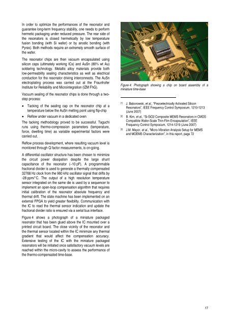
Figure 4 shows a photograph of a m<strong>in</strong>iature packaged<br />
resonator that has been glued above the IC mounted over a<br />
pr<strong>in</strong>ted circuit board. The close vic<strong>in</strong>ity of the resonator and<br />
the thermal sensor located with<strong>in</strong> the IC m<strong>in</strong>imize any thermal<br />
gradient that would affect the compensation accuracy.<br />
Extensive test<strong>in</strong>g of the IC with the m<strong>in</strong>iature packaged<br />
resonators will be <strong>in</strong>itiated once satisfactory vacuum levels are<br />
reached with<strong>in</strong> the micro-cavity to assess the performance of<br />
the thermo-compensated time-base.<br />
Figure 4: Photograph show<strong>in</strong>g a chip on board assembly of a<br />
m<strong>in</strong>iature time-base<br />
[1] J. Baborowski, et al., “Piezoelectrically Activated Silicon<br />
Resonators”, IEEE Frequency Control Symposium, 1210-1213<br />
(June <strong>2007</strong>)<br />
[2] B. Kim, et al., “Si-SiO2 Composite MEMS Resonators <strong>in</strong> CMOS<br />
Compatible Wafer-Scale Th<strong>in</strong>-Film Encapsulation”, IEEE<br />
Frequency Control Symposium, 1214-1219 (June <strong>2007</strong>)<br />
[3] J.M. Mayor, et al., “Micro-Vibration Analysis Setup for MEMS<br />
and MOEMS Characterization”, <strong>in</strong> this report, page 72<br />
17