research activities in 2007 - CSEM
research activities in 2007 - CSEM
research activities in 2007 - CSEM

Create successful ePaper yourself
Turn your PDF publications into a flip-book with our unique Google optimized e-Paper software.
Micro-Vibration Analysis Setup for MEMS and MOEMS Characterization<br />
J.-M. Mayor, I. Kjelberg, P. Masa, J. Babarowski<br />
A new test station for the measurement of the resonance frequencies of micro-structures is presented. The vibrations are detected either along the<br />
optical direction or perpendicular to it. The absolute resonance frequency is measured with accuracy better than 5 ppm (changes to 1 ppm). In<br />
2008, the station will be equipped with a climatic and a vacuum chamber to measure the samples <strong>in</strong> a controlled environment.<br />
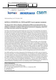
Figure 1: The test station with a 100 mm wafer<br />
Measurement of the resonance frequency of test samples with<br />
a high accuracy is required <strong>in</strong> order to ascerta<strong>in</strong> mechanical<br />
properties of the materials used, for <strong>in</strong>stance Young’s<br />
modulus as a function of temperature.<br />
The need to have a reliable and cost-effective system suitable<br />
for operation <strong>in</strong> the clean room production area as quality<br />
control dur<strong>in</strong>g the manufactur<strong>in</strong>g process was recognized.<br />
Based on <strong>CSEM</strong>’s development, the system was built by the<br />
company OCB (CH-Mar<strong>in</strong>) with commercially available<br />
standard mechanical blocks so that any change of the optical<br />
configuration could easily be implemented (see Figure 1).<br />
Particular attention has been given to the mechanical rigidity<br />
of the system. Contrary to usual microscopes, where the f<strong>in</strong>e<br />
adjustment is done by mov<strong>in</strong>g the whole optical system, here<br />
the f<strong>in</strong>e adjustment is performed by a small vertical shift of the<br />
objective only. As a matter of fact, the stability of the<br />
observ<strong>in</strong>g system has been checked and found to be better<br />
than 1 nanometer <strong>in</strong> a one hour observ<strong>in</strong>g time. For this<br />
purpose, the method developed by P. Masa with<strong>in</strong> the frame<br />
of the ENCODER project [1] was used.<br />
Microscope objectives with a magnify<strong>in</strong>g power of 5 x, 10 x<br />
and 20 x and a work<strong>in</strong>g distance of 39 mm also allows the test<br />
of encapsulated microsystems. The work<strong>in</strong>g distance can be<br />
further enhanced with the use of commercially available relay<br />
lenses which permit operation of the measur<strong>in</strong>g equipment<br />
when the test sample is <strong>in</strong> a vacuum or climatic chamber (to<br />
be developed <strong>in</strong> 2008).<br />
The <strong>in</strong>vestigated test structures are expected to have quality<br />
factors well above 1’000 therefore an excitation with amplitude<br />
<strong>in</strong> the nanometer range, obta<strong>in</strong>ed with only 1 V on a PZT<br />
stack actuator, will br<strong>in</strong>g test structures <strong>in</strong>to resonance with<br />
fully detectable movement signals. The frequency response<br />
can be obta<strong>in</strong>ed with a SRL lock-<strong>in</strong>, a HP spectrum analyzer<br />
72<br />
and a rubidium stabilized clock, directly connected to the<br />
station.<br />
The probe laser wavelength is above 650 nm so that the color<br />
render<strong>in</strong>g of the microscope is not affected by the dichroic<br />
beam splitter <strong>in</strong> the observation path of the camera: any<br />
defect of the test sample is clearly recognizable on the<br />
display.<br />
The detection of the movement can be measured either along<br />
the optical direction (perpendicular to the wafer plane) or<br />
perpendicular to it (<strong>in</strong> the wafer plane).<br />
• For the detection of the movement <strong>in</strong> a horizontal plane<br />
the <strong>in</strong>vestigated part must have a sharp edge on which the<br />
laser beam is focused. Any movement of the edge will<br />
change the amount of light reflected or transmitted.<br />
• For the detection along the optical axis a surface of<br />
reasonable optical quality is needed. Then an optical fiber<br />
is put at the image po<strong>in</strong>t of the laser spot. Any deviation <strong>in</strong><br />
height will affect the size of the spot and thus the quantity<br />
of light transmitted <strong>in</strong>to the optical fiber.<br />
With both configurations absolute resonance frequencies of<br />
test samples and of microsystem structures were determ<strong>in</strong>ed<br />
with accuracy better than 5 ppm. Resonance frequency<br />
change (for <strong>in</strong>stance with temperature) can be detected with a<br />
sensitivity down to 1 ppm by measur<strong>in</strong>g the phase difference<br />
between the excitation and the position signal.<br />
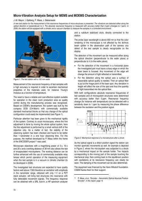
Figure 2: Mechanical response of a microstructure after a shock<br />
As the optical signal is a direct position signal the station can<br />
monitor aperiodic movements as well. An example is depicted<br />
<strong>in</strong> Figure 2, where the microsystem was subjected to a shock<br />
by a mechanical impact on the sample holder. Two impacts<br />
correspond<strong>in</strong>g to the mov<strong>in</strong>g part of the sample touch<strong>in</strong>g the<br />
mechanical stop, then com<strong>in</strong>g back to the equilibrium position<br />
with oscillations at its resonance frequency can clearly be<br />
seen. The damp<strong>in</strong>g of the movement can be also determ<strong>in</strong>ed.<br />
The equipment was f<strong>in</strong>anced by the Hans Wilsdorf foundation.<br />
<strong>CSEM</strong> thanks them for their support.<br />
[1] P. Masa, et al., “Encoder – Nanometric Optical Absolute Position<br />
Encoder”, <strong>in</strong> this report, page 14