

Logic selection guide 2016
1Sk34oD
1Sk34oD

Create successful ePaper yourself
Turn your PDF publications into a flip-book with our unique Google optimized e-Paper software.
LIVE INSERTION<br />
What it does<br />
Enables the installation or removal of a board while the<br />
system is powered up.<br />
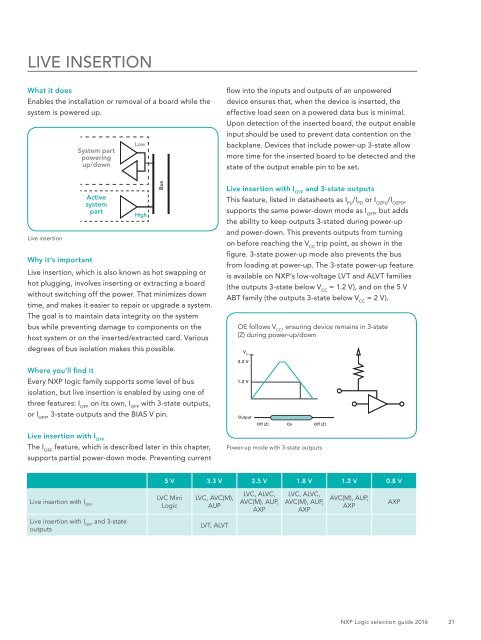
System part<br />
powering<br />
up/down<br />
Low<br />
flow into the inputs and outputs of an unpowered<br />
device ensures that, when the device is inserted, the<br />
effective load seen on a powered data bus is minimal.<br />
Upon detection of the inserted board, the output enable<br />
input should be used to prevent data contention on the<br />
backplane. Devices that include power-up 3-state allow<br />
more time for the inserted board to be detected and the<br />
state of the output enable pin to be set.<br />
Live insertion<br />
Why it’s important<br />
Active<br />
system<br />
part<br />
High<br />
Live insertion, which is also known as hot swapping or<br />
hot plugging, involves inserting or extracting a board<br />
without switching off the power. That minimizes down<br />
time, and makes it easier to repair or upgrade a system.<br />
The goal is to maintain data integrity on the system<br />
bus while preventing damage to components on the<br />
host system or on the inserted/extracted card. Various<br />
Bus<br />
degrees of bus isolation makes this possible.<br />
Live insertion with I OFF<br />
and 3-state outputs<br />
This feature, listed in datasheets as I PU<br />
/I PD<br />
or I OZPU<br />
/I OZPD<br />
,<br />
supports the same power-down mode as I OFF<br />
, but adds<br />
the ability to keep outputs 3-stated during power-up<br />
and power-down. This prevents outputs from turning<br />
on before reaching the V CC<br />
trip point, as shown in the<br />
figure. 3-state power-up mode also prevents the bus<br />
from loading at power-up. The 3-state power-up feature<br />
is available on NXP’s low-voltage LVT and ALVT families<br />
(the outputs 3-state below V CC<br />
= 1.2 V), and on the 5 V<br />
ABT family (the outputs 3-state below V CC<br />
= 2 V).<br />
OE follows V CC<br />
, ensuring device remains in 3-state<br />
(Z) during power-up/down<br />
V cc<br />
Where you’ll find it<br />
3.3 V<br />
Every NXP logic family supports some level of bus<br />
1.2 V<br />
isolation, but live insertion is enabled by using one of<br />
three features: I OFF<br />
on its own, I OFF<br />
with 3-state outputs,<br />
or I OFF<br />
, 3-state outputs and the BIAS V pin.<br />
Output<br />
Off (Z)<br />
On<br />
Off (Z)<br />
Live insertion with I OFF<br />
The I OFF<br />
feature, which is described later in this chapter,<br />
supports partial power-down mode. Preventing current<br />
Power-up mode with 3-state outputs<br />
5 V 3.3 V 2.5 V 1.8 V 1.2 V 0.8 V<br />
Live insertion with I OFF<br />
LVC Mini<br />
<strong>Logic</strong><br />
LVC, AVC(M),<br />
AUP<br />
LVC, ALVC,<br />
AVC(M), AUP,<br />
AXP<br />
LVC, ALVC,<br />
AVC(M), AUP,<br />
AXP<br />
AVC(M), AUP,<br />
AXP<br />
AXP<br />
Live insertion with I OFF<br />
and 3-state<br />
outputs<br />
LVT, ALVT<br />
NXP <strong>Logic</strong> <strong>selection</strong> <strong>guide</strong> <strong>2016</strong><br />
21