- Page 1:
A Design Guide for Implementers and
- Page 4 and 5:
LID Manual for Michigan Page ii
- Page 6 and 7:
Shawn Keenan, City of Auburn Hills
- Page 8 and 9:
Appendix G: Stormwater Management P
- Page 10 and 11:
Figure 7.18 Filter with infiltratio
- Page 12 and 13:
Table 7.9 Definitions of Wetland Ve
- Page 14 and 15:
How this manual is organized This m
- Page 16 and 17:
discuss a new development. The staf
- Page 18 and 19:
In a natural woodland or meadow in
- Page 20 and 21:
Almost all components of the urban
- Page 22 and 23:
Benefits of implementing LID Implem
- Page 24 and 25:
Table 2.2 Summary of Cost Compariso
- Page 26 and 27:
Getting started with LID LID can be
- Page 28 and 29:
Precipitation also varies slightly
- Page 30 and 31:
Figure 3.4 Soil Freezing in Lower M
- Page 32 and 33:
Figure 3.6 Michigan Surficial Geolo
- Page 34 and 35:
Most soils in Michigan are classifi
- Page 36 and 37:
Table 3.3 Representative Cation Exc
- Page 38 and 39:
There is currently no single broadl
- Page 40 and 41:
Wellhead protection areas/ public w
- Page 42 and 43:
Table 3.4 Michigan Rivers and Strea
- Page 44 and 45:
References * Bailey, R.M and G.R. S
- Page 46 and 47:
LID Manual for Michigan - Chapter 3
- Page 48 and 49:
Following are sample goals and poli
- Page 50 and 51:
Develop regulations that encourage/
- Page 52 and 53:
Construction activity • Minimize
- Page 54 and 55:
Street sweeping in Bloomfield Towns
- Page 56 and 57:
Resistance from internal sources an
- Page 58 and 59:
Site constraints that may pose chal
- Page 60 and 61:
Entity Stormwater Jurisdiction Coun
- Page 62 and 63:
Step 1: Property acquisition and us
- Page 64 and 65:
can be incorporated into the develo
- Page 66 and 67:
Step 3: Integrate municipal, county
- Page 68 and 69:
LID Manual for Michigan - Chapter 5
- Page 70 and 71:
BMP Selection Process This chapter
- Page 72 and 73:
Case Study: Title The second page o
- Page 74 and 75:
Case Study: Pokagon Band of Potawat
- Page 76 and 77:
Figure 6.2 Conventional development
- Page 78 and 79:
Designer/Reviewer Checklist for Clu
- Page 80 and 81:
LID Manual for Michigan - Chapter 6
- Page 82 and 83:
Case Study: Minimizing soil compact
- Page 84 and 85:
4. Topsoil stockpiling and storage
- Page 86 and 87:
References Hanks, D. and Lewandowsk
- Page 88 and 89:
Case Study: Longmeadow Development
- Page 90 and 91:
Applications Minimizing the total d
- Page 92 and 93:
Criteria to Receive Credits for Min
- Page 94 and 95:
LID Manual for Michigan - Chapter 6
- Page 96 and 97:
Case Study: Marywood Health Center
- Page 98 and 99:
Design Considerations 1. Identify n
- Page 100 and 101:
References Center for Watershed Pro
- Page 102 and 103:
Case Study: Macomb County Public Wo
- Page 104 and 105:
Zone 3: Also termed the “outer zo
- Page 106 and 107:
• Limit clearing and grading of f
- Page 108 and 109:
LID Manual for Michigan - Chapter 6
- Page 110 and 111:
Case Study: Western Michigan Univer
- Page 112 and 113:
Protection of sensitive areas in re
- Page 114 and 115:
then weightings of potential develo
- Page 116 and 117:
Floodplains • Design the project
- Page 118 and 119:
References Arendt, Randall G. Growi
- Page 120 and 121:
Case Study: Willard Beach Implement
- Page 122 and 123:
Table 6.2 Narrow residential street
- Page 124 and 125:
Parking Parking lots often comprise
- Page 126 and 127:
Designer/Reviewer Checklist for Red
- Page 128 and 129:
Case Study: Saugatuck Center for th
- Page 130 and 131:
In addition to directing runoff to
- Page 132 and 133:
Designer/Reviewer Checklist for Dis
- Page 134 and 135:
Runoff Volume/ Infiltration Runoff
- Page 136 and 137:
Figure 7.1 Structural BMP Selection
- Page 138 and 139:
In general, the techniques describe
- Page 140 and 141:
Table 7.3 Additional BMP considerat
- Page 142 and 143:
Maintenance Provides guidance on re
- Page 144 and 145:
Case Study: Grayling Stormwater Pro
- Page 146 and 147:
Figure 7.5 illustrates a schematic
- Page 148 and 149:
Flow inlet: Curbs and curb cuts Cur
- Page 150 and 151:
Roads and highways Figure 7.13 show
- Page 152 and 153:
Design Considerations Bioretention
- Page 154 and 155:
7. Planting periods will vary but,
- Page 156 and 157:
Construction Guidelines The followi
- Page 158 and 159:
Designer/Reviewer Checklist for Rai
- Page 160 and 161:
Case Study: Stormwater Capture with
- Page 162 and 163:
Ford Rouge Plant cistern Vertical s
- Page 164 and 165:
Design Considerations Design and in
- Page 166 and 167:
the tank can accommodate.) (www.sta
- Page 168 and 169:
References “Black Vertical Storag
- Page 170 and 171:
Case Study: Constructed Linear Sand
- Page 172 and 173:
Surface non-vegetated filter A surf
- Page 174 and 175:
Large subsurface filter Large Subsu
- Page 176 and 177:
would modestly increase constructio
- Page 178 and 179:
During inspection the following con
- Page 180 and 181:
References Atlanta Regional Commiss
- Page 182 and 183:
Site Factors Type Basin Bottom Rela
- Page 184 and 185:
LID Manual for Michigan - Chapter 7
- Page 186 and 187: Variations For this manual, detenti
- Page 188 and 189: Precast concrete vault Source: Amer
- Page 190 and 191: surface into the pond to a maximum
- Page 192 and 193: sink for pollutants and generally h
- Page 194 and 195: The presettlement and post-developm
- Page 196 and 197: wet pond and constructed wetland op
- Page 198 and 199: ackfilling operation should driven
- Page 200 and 201: Designer/Reviewer Checklist for Dry
- Page 202 and 203: Designer/Reviewer Checklist for Con
- Page 204 and 205: References AMEC Earth and Environme
- Page 206 and 207: Key Design Features • Depth to wa
- Page 208 and 209: Case Study: Saugatuck Center for th
- Page 210 and 211: Infiltration basins, subsurface inf
- Page 212 and 213: Figure 7.24 Cross-section of dry we
- Page 214 and 215: • The soil mantle should be prese
- Page 216 and 217: Additional design considerations fo
- Page 218 and 219: • Though roofs are generally not
- Page 220 and 221: Subsurface infiltration bed Source:
- Page 222 and 223: Stormwater Functions and Calculatio
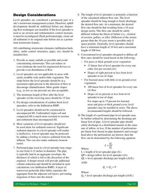
- Page 224 and 225: • Protect the infiltration area f
- Page 226 and 227: Additional Construction Guidelines
- Page 228 and 229: Designer/Reviewer Checklist for Inf
- Page 230 and 231: References AMEC Earth and Environme
- Page 232 and 233: LID Manual for Michigan - Chapter 7
- Page 234 and 235: Case Study: Washtenaw County West S
- Page 238 and 239: 3. Inspect the filter strip and the
- Page 240 and 241: References Hathaway, Jon and Hunt,
- Page 242 and 243: Case Study: Black River Heritage Tr
- Page 244 and 245: Figure 7.31 Native meadow species c
- Page 246 and 247: Applications • Residential - Nati
- Page 248 and 249: 5. Amend soil: In those sites where
- Page 250 and 251: Water quality improvement Landscape
- Page 252 and 253: References Arendt, R. Growing Green
- Page 254 and 255: Case Study: Grand Valley State Univ
- Page 256 and 257: Staging, construction practices, an
- Page 258 and 259: Reinforced turf/gravel Reinforced t
- Page 260 and 261: 4. Pervious pavement and infiltrati
- Page 262 and 263: 12. Proper pervious pavement applic
- Page 264 and 265: Figure 7.40 Open-graded, clean, coa
- Page 266 and 267: Repairs • Surface should never be
- Page 268 and 269: References Adams, Michele. “Porou
- Page 270 and 271: Case Study: Michigan Avenue Streets
- Page 272 and 273: Native vegetation should be used in
- Page 274 and 275: Design Considerations • Suggested
- Page 276 and 277: oxes, etc. should be installed in a
- Page 278 and 279: References Stormwater Management Gu
- Page 280 and 281: Case Study: Nankin Mills Interpreti
- Page 282 and 283: Figure 7.45 Schematic of a three-zo
- Page 284 and 285: 3. Analyze site’s vegetative feat
- Page 286 and 287:
Black River Heritage Trail and Wate
- Page 288 and 289:
Table 7.14 Tree spacing per acre Sp
- Page 290 and 291:
4. Stable debris As Zone 1 reaches
- Page 292 and 293:
References Alliance for the Chesape
- Page 294 and 295:
Case Study: Ann Arbor District Libr
- Page 296 and 297:
• Major compaction - Deep compact
- Page 298 and 299:
e. Add six inches compost or other
- Page 300 and 301:
References “Achieving the Post-Co
- Page 302 and 303:
Case Study: Wayne County, MI Ford R
- Page 304 and 305:
slope needs to be determined. This
- Page 306 and 307:
Figure 7.52 Sandy soils with HSG Gr
- Page 308 and 309:
Figure 7.56 Clay Loam, Silty Clay o
- Page 310 and 311:
• Guidance information, usually i
- Page 312 and 313:
LID Manual for Michigan - Chapter 7
- Page 314 and 315:
Case Study: City of Battle Creek Ci
- Page 316 and 317:
Table 7.16 Vegetated roof types Ext
- Page 318 and 319:
Dual media assemblies Dual media (F
- Page 320 and 321:
Over a period of time roots can dam
- Page 322 and 323:
Technical requirements Root resista
- Page 324 and 325:
Stormwater Functions and Calculatio
- Page 326 and 327:
Designer/Reviewer Checklist for Veg
- Page 328 and 329:
Case Study: Meadowlake Farms Bioswa
- Page 330 and 331:
lower flows (two-year storm) to dra
- Page 332 and 333:
Stone check dams Source: Road Commi
- Page 334 and 335:
Table 7.18 Permanent stabilization
- Page 336 and 337:
Peak rate mitigation Vegetated swal
- Page 338 and 339:
Designer/Reviewer Checklist for Veg
- Page 340 and 341:
LID Manual for Michigan - Chapter 7
- Page 342 and 343:
Case Study: LaVista Storm Drain Pro
- Page 344 and 345:
Basket type inserts Basket type ins
- Page 346 and 347:
Maintenance is crucial to the effec
- Page 348 and 349:
Roadway design, construction, and m
- Page 350 and 351:
• Vegetated systems such as grass
- Page 352 and 353:
Of the options explored, the study
- Page 354 and 355:
Figure 8.3 Tree planting detail Sou
- Page 356 and 357:
Opportunities for MPOs Metropolitan
- Page 358 and 359:
Construction on the project began i
- Page 360 and 361:
The following are examples of imple
- Page 362 and 363:
Horizontal grates can be added to a
- Page 364 and 365:
East Hills Center City of Grand Rap
- Page 366 and 367:
Implementing LID in High Risk Areas
- Page 368 and 369:
References AASHTO Center for Enviro
- Page 370 and 371:
LID Design Criteria Defining the hy
- Page 372 and 373:
Flood control Flood control is base
- Page 374 and 375:
Table 9.1 90 Percent Nonexceedance
- Page 376 and 377:
Initial abstraction (I a ) includes
- Page 378 and 379:
The Curve Number Method is less acc
- Page 380 and 381:
I = the average rainfall intensity
- Page 382 and 383:
Table 9.4 Rainfall Events of 24-Hou
- Page 384 and 385:
• Proceed to Flow Chart B, Peak R
- Page 386 and 387:
FLOW CHART A Stormwater Calculation
- Page 388 and 389:
Excessively drained soils may requi
- Page 390 and 391:
Worksheet 2. Sensitive Natural Reso
- Page 392 and 393:
WORKSHEET 4. Calculations for Volum
- Page 394 and 395:
WORKSHEET 6. SMALL SITE / SMALL IMP
- Page 396 and 397:
WORKSHEET 8. WATER QUALITY WORKSHEE
- Page 398 and 399:
Reese, S. and J. Lee. “Summary of
- Page 400 and 401:
ing Department. Most maintenance co
- Page 402 and 403:
The Hydrotech Garden Roof Assembly
- Page 404 and 405:
Bioswales provide infiltration of s
- Page 406 and 407:
The Ingham County Drain Commissione
- Page 408 and 409:
Constructed wetland The lowest port
- Page 410 and 411:
LID Manual for Michigan - Chapter 1
- Page 412 and 413:
LID Manual for Michigan - Appendix
- Page 414 and 415:
Check dam Cistern Clustering Combin
- Page 416 and 417:
H:V Horizontal to vertical ratio. H
- Page 418 and 419:
Planter box Pervious pavement Phase
- Page 420 and 421:
Total phosphorous (TP) The total am
- Page 422 and 423:
Ecoregion recommendations are also
- Page 424 and 425:
Zone A Planting Zone = two-to-four
- Page 426 and 427:
Zone C Planting Zone = zero-to-two
- Page 428 and 429:
Representative Zone C Species Cardi
- Page 430 and 431:
Botanical Name Common Name Height C
- Page 432 and 433:
Zone E Planting Zone = four-to-18 i
- Page 434 and 435:
Representative Zone E Species Tall
- Page 436 and 437:
Botanical Name Common Name Height C
- Page 438 and 439:
Zone G Planter Box Plantings Althou
- Page 440 and 441:
Zone H Vegetated Roof Plantings Res
- Page 442 and 443:
LID Manual for Michigan - Appendix
- Page 444 and 445:
Pervious Berms (Vegetated Filter St
- Page 446 and 447:
Vegetated roofs Some key components
- Page 448 and 449:
LID Manual for Michigan - Appendix
- Page 450 and 451:
Step 1. Background evaluation Prior
- Page 452 and 453:
Methodology for double-ring infiltr
- Page 454 and 455:
Step 4. Use design considerations p
- Page 456 and 457:
LID Manual for Michigan - Appendix
- Page 458 and 459:
Detention BMP Inspection Checklist*
- Page 460 and 461:
Infiltration BMPs Inspection Checkl
- Page 462 and 463:
Bioretention Inspection Checklist*
- Page 464 and 465:
Bioswale, Filter Strip Inspection C
- Page 466 and 467:
LID Manual for Michigan - Appendix
- Page 468 and 469:
6. The [Community] or its designee
- Page 470 and 471:
STATE OF MICHIGAN ) ) ss. COUNTY OF
- Page 472 and 473:
Exhibit B - Location Map (Sample) S
- Page 474 and 475:
LID Manual for Michigan - Appendix
- Page 476 and 477:
LID Manual for Michigan - Appendix
- Page 478 and 479:
LID Manual for Michigan - Appendix
- Page 480 and 481:
LID Manual for Michigan - Appendix
- Page 482 and 483:
LID Manual for Michigan - Appendix
- Page 484 and 485:
LID Manual for Michigan - Appendix
- Page 486 and 487:
LID Manual for Michigan - Appendix
- Page 488 and 489:
LID Manual for Michigan - Appendix
- Page 490 and 491:
• Stormwater runoff, soil erosion
- Page 492 and 493:
Retention. A holding system for sto
- Page 494 and 495:
ARTICLE IV. STORMWATER PLAN REQUIRE
- Page 496 and 497:
The particular facilities and measu
- Page 498 and 499:
10. Rainfall Frequency Atlas of the
- Page 500 and 501:
Table H.2 Pre-Treatment Options for
- Page 502 and 503:
f. Complete development agreements
- Page 504 and 505:
must be submitted to the Michigan D
- Page 506 and 507:
C. Construction Plans shall be revi
- Page 508 and 509:
fine for each day. The rights and r
- Page 512:
Southeast Michigan Council of Gover