Low Impact Development Manual for Michigan - OSEH - University ...
Low Impact Development Manual for Michigan - OSEH - University ...
Low Impact Development Manual for Michigan - OSEH - University ...

You also want an ePaper? Increase the reach of your titles
YUMPU automatically turns print PDFs into web optimized ePapers that Google loves.
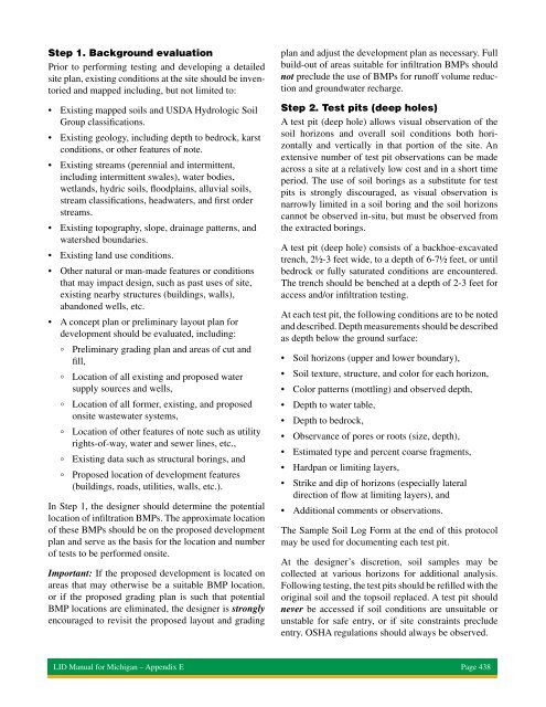
Step 1. Background evaluation<br />
Prior to per<strong>for</strong>ming testing and developing a detailed<br />
site plan, existing conditions at the site should be inventoried<br />
and mapped including, but not limited to:<br />
• Existing mapped soils and USDA Hydrologic Soil<br />
Group classifications.<br />
• Existing geology, including depth to bedrock, karst<br />
conditions, or other features of note.<br />
• Existing streams (perennial and intermittent,<br />
including intermittent swales), water bodies,<br />
wetlands, hydric soils, floodplains, alluvial soils,<br />
stream classifications, headwaters, and first order<br />
streams.<br />
• Existing topography, slope, drainage patterns, and<br />
watershed boundaries.<br />
• Existing land use conditions.<br />
• Other natural or man-made features or conditions<br />
that may impact design, such as past uses of site,<br />
existing nearby structures (buildings, walls),<br />
abandoned wells, etc.<br />
• A concept plan or preliminary layout plan <strong>for</strong><br />
development should be evaluated, including:<br />
° Preliminary grading plan and areas of cut and<br />
fill,<br />
° Location of all existing and proposed water<br />
supply sources and wells,<br />
° Location of all <strong>for</strong>mer, existing, and proposed<br />
onsite wastewater systems,<br />
° Location of other features of note such as utility<br />
rights-of-way, water and sewer lines, etc.,<br />
° Existing data such as structural borings, and<br />
° Proposed location of development features<br />
(buildings, roads, utilities, walls, etc.).<br />
In Step 1, the designer should determine the potential<br />
location of infiltration BMPs. The approximate location<br />
of these BMPs should be on the proposed development<br />
plan and serve as the basis <strong>for</strong> the location and number<br />
of tests to be per<strong>for</strong>med onsite.<br />
Important: If the proposed development is located on<br />
areas that may otherwise be a suitable BMP location,<br />
or if the proposed grading plan is such that potential<br />
BMP locations are eliminated, the designer is strongly<br />
encouraged to revisit the proposed layout and grading<br />
plan and adjust the development plan as necessary. Full<br />
build-out of areas suitable <strong>for</strong> infiltration BMPs should<br />
not preclude the use of BMPs <strong>for</strong> runoff volume reduction<br />
and groundwater recharge.<br />
Step 2. Test pits (deep holes)<br />
A test pit (deep hole) allows visual observation of the<br />
soil horizons and overall soil conditions both horizontally<br />
and vertically in that portion of the site. An<br />
extensive number of test pit observations can be made<br />
across a site at a relatively low cost and in a short time<br />
period. The use of soil borings as a substitute <strong>for</strong> test<br />
pits is strongly discouraged, as visual observation is<br />
narrowly limited in a soil boring and the soil horizons<br />
cannot be observed in-situ, but must be observed from<br />
the extracted borings.<br />
A test pit (deep hole) consists of a backhoe-excavated<br />
trench, 2½-3 feet wide, to a depth of 6-7½ feet, or until<br />
bedrock or fully saturated conditions are encountered.<br />
The trench should be benched at a depth of 2-3 feet <strong>for</strong><br />
access and/or infiltration testing.<br />
At each test pit, the following conditions are to be noted<br />
and described. Depth measurements should be described<br />
as depth below the ground surface:<br />
• Soil horizons (upper and lower boundary),<br />
• Soil texture, structure, and color <strong>for</strong> each horizon,<br />
• Color patterns (mottling) and observed depth,<br />
• Depth to water table,<br />
• Depth to bedrock,<br />
• Observance of pores or roots (size, depth),<br />
• Estimated type and percent coarse fragments,<br />
• Hardpan or limiting layers,<br />
• Strike and dip of horizons (especially lateral<br />
direction of flow at limiting layers), and<br />
• Additional comments or observations.<br />
The Sample Soil Log Form at the end of this protocol<br />
may be used <strong>for</strong> documenting each test pit.<br />
At the designer’s discretion, soil samples may be<br />
collected at various horizons <strong>for</strong> additional analysis.<br />
Following testing, the test pits should be refilled with the<br />
original soil and the topsoil replaced. A test pit should<br />
never be accessed if soil conditions are unsuitable or<br />
unstable <strong>for</strong> safe entry, or if site constraints preclude<br />
entry. OSHA regulations should always be observed.<br />
LID <strong>Manual</strong> <strong>for</strong> <strong>Michigan</strong> – Appendix E Page 438