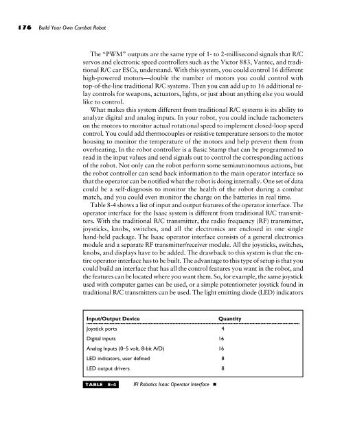
- Page 2 and 3:
Build Your Own Combat Robot Pete Mi
- Page 4 and 5:
For more information about this boo
- Page 6 and 7:
Contents For more information about
- Page 8 and 9:
Current Ratings, 129 How It All Wor
- Page 10 and 11:
Object Detector, 290 Sensor Integra
- Page 12 and 13:
Acknowledgments We would like to th
- Page 14 and 15:
Introduction Some kids spend their
- Page 16 and 17:
About the Authors xv About the Auth
- Page 18:
This page intentionally left blank.
- Page 21 and 22:
2 ELCOME to the world of combat rob
- Page 23 and 24:
4 Build Your Own Combat Robot FIGUR
- Page 25 and 26:
6 Build Your Own Combat Robot aroun
- Page 27 and 28:
8 Build Your Own Combat Robot FIGUR
- Page 29 and 30:
10 Build Your Own Combat Robot Pinb
- Page 31 and 32:
12 Build Your Own Combat Robot FIGU
- Page 33 and 34:
14 Build Your Own Combat Robot Seas
- Page 35 and 36:
16 Build Your Own Combat Robot Robo
- Page 37:
18 Build Your Own Combat Robot In t
- Page 41 and 42:
22 S we said in Chapter 1, it’s g
- Page 43 and 44:
24 Build Your Own Combat Robot Even
- Page 45 and 46:
26 Build Your Own Combat Robot FIGU
- Page 47 and 48:
28 Build Your Own Combat Robot FIGU
- Page 49 and 50:
30 Build Your Own Combat Robot Befo
- Page 51 and 52:
32 Build Your Own Combat Robot What
- Page 53 and 54:
34 Build Your Own Combat Robot Test
- Page 55 and 56:
36 Build Your Own Combat Robot S af
- Page 57:
38 Build Your Own Combat Robot Ther
- Page 61 and 62:
42 OVING is what many might call a
- Page 63 and 64:
44 Build Your Own Combat Robot FIGU
- Page 65 and 66:
46 Build Your Own Combat Robot Bot
- Page 67 and 68:
48 Build Your Own Combat Robot FIGU
- Page 69 and 70:
50 Build Your Own Combat Robot FIGU
- Page 71 and 72:
52 Build Your Own Combat Robot You
- Page 73 and 74:
54 Build Your Own Combat Robot FIGU
- Page 75 and 76:
56 Build Your Own Combat Robot Thro
- Page 77 and 78:
58 Build Your Own Combat Robot FIGU
- Page 80 and 81:
chapter Motor Selection and Perform
- Page 82 and 83:
Chapter 4: Motor Selection and Perf
- Page 84 and 85:
FIGURE 4-1 Typical motor performanc
- Page 86 and 87:
Determining the Motor Constants Cha
- Page 88 and 89:
FIGURE 4-2 Heat generated in an ele
- Page 90 and 91:
FIGURE 4-4 Motor power changes by d
- Page 92 and 93:
Chapter 4: Motor Selection and Perf
- Page 94 and 95:
FIGURE 4-7 24-volt, 185 rpm, 896 in
- Page 96:
the robot. If the engine is used to
- Page 99 and 100:
80 LECTRICALLY powered competition
- Page 101 and 102:
82 Build Your Own Combat Robot the
- Page 103 and 104:
84 Build Your Own Combat Robot FIGU
- Page 105 and 106:
86 Build Your Own Combat Robot Comp
- Page 107 and 108:
88 Build Your Own Combat Robot FIGU
- Page 109 and 110:
90 Build Your Own Combat Robot Batt
- Page 111 and 112:
92 Build Your Own Combat Robot You
- Page 113 and 114:
94 Build Your Own Combat Robot Hawk
- Page 115 and 116:
96 Build Your Own Combat Robot FIGU
- Page 117 and 118:
98 Build Your Own Combat Robot Alka
- Page 119:
100 Build Your Own Combat Robot Ins
- Page 123 and 124:
104 NE of the most important consid
- Page 125 and 126:
106 Build Your Own Combat Robot Gra
- Page 127 and 128:
108 Build Your Own Combat Robot FIG
- Page 129 and 130:
110 Build Your Own Combat Robot FIG
- Page 131 and 132:
112 Build Your Own Combat Robot Loc
- Page 133 and 134:
114 Build Your Own Combat Robot FIG
- Page 135 and 136:
116 Build Your Own Combat Robot FIG
- Page 137 and 138:
118 Build Your Own Combat Robot Bel
- Page 139 and 140:
120 Build Your Own Combat Robot V-B
- Page 141 and 142:
122 Build Your Own Combat Robot Mou
- Page 143: 124 Build Your Own Combat Robot Pla
- Page 147 and 148: 128 F batteries are the source of p
- Page 149 and 150: 130 Build Your Own Combat Robot FIG
- Page 151 and 152: 132 Build Your Own Combat Robot FIG
- Page 153 and 154: 134 Build Your Own Combat Robot Dri
- Page 155 and 156: 136 Build Your Own Combat Robot FIG
- Page 157 and 158: 138 Build Your Own Combat Robot FIG
- Page 159 and 160: 140 Build Your Own Combat Robot Rel
- Page 161 and 162: 142 Build Your Own Combat Robot are
- Page 163 and 164: 144 Build Your Own Combat Robot FIG
- Page 165 and 166: 146 Build Your Own Combat Robot You
- Page 167 and 168: 148 Build Your Own Combat Robot FIG
- Page 169 and 170: 150 Build Your Own Combat Robot FIG
- Page 171 and 172: 152 Build Your Own Combat Robot Lik
- Page 173 and 174: 154 Build Your Own Combat Robot At
- Page 176 and 177: chapter Remotely Controlling Your R
- Page 178 and 179: FIGURE 8-1 Wiring and rotational po
- Page 180 and 181: FIGURE 8-2 Futaba’s top of-the-li
- Page 182 and 183: Chapter 8: Remotely Controlling You
- Page 184 and 185: FIGURE 8-4 Typical radio frequency
- Page 186 and 187: Chapter 8: Remotely Controlling You
- Page 188 and 189: Chapter 8: Remotely Controlling You
- Page 190 and 191: FIGURE 8-5 Motor with three capacit
- Page 192 and 193: Chapter 8: Remotely Controlling You
- Page 196 and 197: FIGURE 8-6 Block diagram of Isaac o
- Page 198 and 199: Chapter 8: Remotely Controlling You
- Page 202 and 203: chapter 9 Robot Material and Constr
- Page 204 and 205: Metals Aluminum Chapter 9: Robot Ma
- Page 206 and 207: Stainless Steel Chapter 9: Robot Ma
- Page 208 and 209: Titanium used to solder small brass
- Page 210 and 211: Chapter 9: Robot Material and Const
- Page 212 and 213: Chapter 9: Robot Material and Const
- Page 214 and 215: Welding, Joining, and Fastening We
- Page 216 and 217: place, or some liquid may have ente
- Page 218 and 219: Chapter 9: Robot Material and Const
- Page 220: vibration and bounce around the ins
- Page 223 and 224: 204 ECAUSE robot combat has evolved
- Page 225 and 226: 206 Build Your Own Combat Robot Thi
- Page 227 and 228: 208 Build Your Own Combat Robot Wed
- Page 229 and 230: 210 Build Your Own Combat Robot Wed
- Page 231 and 232: 212 Build Your Own Combat Robot Str
- Page 233 and 234: 214 Build Your Own Combat Robot FIG
- Page 235 and 236: 216 Build Your Own Combat Robot FIG
- Page 237 and 238: 218 Build Your Own Combat Robot FIG
- Page 239 and 240: 220 Build Your Own Combat Robot FIG
- Page 241 and 242: 222 Build Your Own Combat Robot Str
- Page 243 and 244: 224 Build Your Own Combat Robot Str
- Page 245 and 246:
226 Build Your Own Combat Robot Str
- Page 247 and 248:
228 Build Your Own Combat Robot Str
- Page 249 and 250:
230 Build Your Own Combat Robot FIG
- Page 251 and 252:
232 Build Your Own Combat Robot FIG
- Page 253 and 254:
234 Build Your Own Combat Robot FIG
- Page 255:
236 Build Your Own Combat Robot Str
- Page 259 and 260:
240 HE robots described in the book
- Page 261 and 262:
242 Build Your Own Combat Robot Pas
- Page 263 and 264:
244 Build Your Own Combat Robot FIG
- Page 265 and 266:
246 Build Your Own Combat Robot FIG
- Page 267 and 268:
248 Build Your Own Combat Robot tub
- Page 269 and 270:
250 Build Your Own Combat Robot One
- Page 271 and 272:
252 Build Your Own Combat Robot FIG
- Page 273 and 274:
254 Build Your Own Combat Robot FIG
- Page 275 and 276:
256 Build Your Own Combat Robot FIG
- Page 278 and 279:
chapter 12 Robot Brains Copyright 2
- Page 280 and 281:
FIGURE 12-1 From top left to bottom
- Page 282 and 283:
Chapter 12: Robot Brains 263 space
- Page 284 and 285:
FIGURE 12-2 The BoeBot from Paralla
- Page 286 and 287:
Handy Board BotBoard Chapter 12: Ro
- Page 288 and 289:
FIGURE 12-5 Robo-Goose, a robotic g
- Page 290 and 291:
FIGURE 12-8 A fully autonomous robo
- Page 292:
S ummary Chapter 12: Robot Brains 2
- Page 295 and 296:
276 HE referee signals, and my hear
- Page 297 and 298:
278 Build Your Own Combat Robot In
- Page 299 and 300:
280 Build Your Own Combat Robot FIG
- Page 301 and 302:
282 Build Your Own Combat Robot FIG
- Page 303 and 304:
284 Build Your Own Combat Robot FIG
- Page 305 and 306:
286 Build Your Own Combat Robot lef
- Page 307 and 308:
288 Build Your Own Combat Robot FIG
- Page 309 and 310:
290 Build Your Own Combat Robot nex
- Page 311 and 312:
292 Build Your Own Combat Robot Onc
- Page 313 and 314:
294 Build Your Own Combat Robot FIG
- Page 315 and 316:
296 Build Your Own Combat Robot b2
- Page 317 and 318:
298 Build Your Own Combat Robot FIG
- Page 319 and 320:
300 Build Your Own Combat Robot abo
- Page 321 and 322:
302 Build Your Own Combat Robot has
- Page 324 and 325:
chapter 14 Real-Life Robots: Lesson
- Page 326 and 327:
FIGURE 14-1 Chew Toy Chapter 14: Re
- Page 328 and 329:
FIGURE 14-2 Chew Toy with protectiv
- Page 330 and 331:
FIGURE 14-3 Wheel shown bolted to d
- Page 332 and 333:
FIGURE 14-5 Front view with arm dow
- Page 334 and 335:
Final Words Chapter 14: Real-Life R
- Page 336 and 337:
Chapter 14: Real-Life Robots: Lesso
- Page 338 and 339:
Chapter 14: Real-Life Robots: Lesso
- Page 340 and 341:
design all the parts, and Dave did
- Page 342 and 343:
FIGURE 14-12 The 4-inch-tall alumin
- Page 344 and 345:
FIGURE 14-15 Internal view of Live
- Page 346:
Chapter 14: Real-Life Robots: Lesso
- Page 349 and 350:
330 The Future of Robot Combat The
- Page 351:
332 Build Your Own Combat Robot the
- Page 355 and 356:
336 NLESS you’re building an exac
- Page 357 and 358:
338 Build Your Own Combat Robot ■
- Page 359:
340 Build Your Own Combat Robot the
- Page 363 and 364:
344 S promised, following are some
- Page 365 and 366:
346 Build Your Own Combat Robot ■
- Page 367 and 368:
348 Build Your Own Combat Robot ■
- Page 369 and 370:
350 Build Your Own Combat Robot Mic
- Page 371:
352 Build Your Own Combat Robot ■
- Page 375 and 376:
356 OLLOWING are formulas that you
- Page 377 and 378:
358 Index 1BDI, 272 1/4 wave antenn
- Page 379 and 380:
360 Build Your Own Combat Robot Bea
- Page 381 and 382:
362 Build Your Own Combat Robot fin
- Page 383 and 384:
364 Build Your Own Combat Robot D D
- Page 385 and 386:
366 Build Your Own Combat Robot rad
- Page 387 and 388:
368 Build Your Own Combat Robot sec
- Page 389 and 390:
370 Build Your Own Combat Robot var
- Page 391 and 392:
372 Build Your Own Combat Robot Sha
- Page 393 and 394:
374 Build Your Own Combat Robot RFI
- Page 395 and 396:
sources of robot parts, 35 top ten
- Page 397 and 398:
378 Build Your Own Combat Robot Spo
- Page 399 and 400:
380 Build Your Own Combat Robot U U
- Page 401:
INTERNATIONAL CONTACT INFORMATION A


