

chapter 3 rigid pavement - DOT On-Line Publications - Department ...
chapter 3 rigid pavement - DOT On-Line Publications - Department ...
chapter 3 rigid pavement - DOT On-Line Publications - Department ...

Create successful ePaper yourself
Turn your PDF publications into a flip-book with our unique Google optimized e-Paper software.
DESIGN OF LENGTH<br />
Studies have shown that <strong>pavement</strong> thickness, base stiffness, and climate affect<br />
the maximum anticipated joint spacing beyond which transverse cracking can be<br />
expected [2]. Research indicates that there is a general relationship between<br />
the ratio of slab length (L) to the radius of relative stiffness (e) and<br />
transverse cracking. The radius of relative stiffness is a term defined by<br />
Westergaard to quantify the relationship between the stiffness of the<br />
foundation and the flexural stiffness of the slab. The radius of relative<br />
stiffness has a lineal dimension and is determined by the following equation:<br />
e - [Eh3/12k(I-r2)]0~'s<br />
where<br />
e - radius of relative stiffness (in.)<br />
E = concrete modulus of elasticity<br />
(psi.)<br />
h - <strong>pavement</strong> thickness (in.)<br />
l - Poisson's ratio of the <strong>pavement</strong><br />
k - modulus of subgrade reaction (pci.)<br />
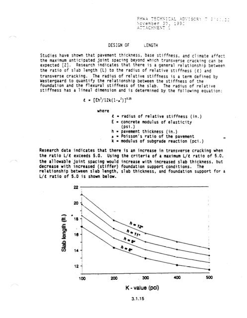
Research data indicates that there is an increase in transverse cracking when<br />
the ratio L/e exceeds 5.0. Using the criteria of a maximum L/C ratio of 5.0,<br />
the allowable.joint spacing would increase with increased slab thickness, but<br />
decrease with increased (stiffer) foundation support conditions. The<br />
relationship between slab length, slab thickness, and foundation support for a<br />
L/C ratio of 5.0 is shown below.<br />
16<br />
200<br />
,300<br />
K - value (pci)<br />
3.1-.15


