chapter 3 rigid pavement - DOT On-Line Publications - Department ...
chapter 3 rigid pavement - DOT On-Line Publications - Department ...
chapter 3 rigid pavement - DOT On-Line Publications - Department ...
You also want an ePaper? Increase the reach of your titles
YUMPU automatically turns print PDFs into web optimized ePapers that Google loves.
_i -.<br />
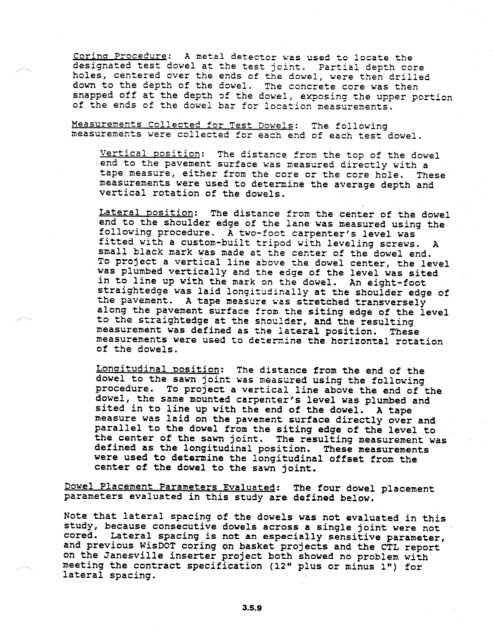
Corinu Procedure: A metal detector was used to locate the<br />
designated test dowel at the test joint. Partial depth core<br />
holes, centered over the ends of the dowel, were then drilled<br />
down to the depth of the dowel. The concrete core was then<br />
snapped off at the depth of the dowel, exposing the upper portion<br />
of the ends of the dowel bar for location measurements.<br />
Measurements Collected for Test Dowels: The following<br />
measurements were collected for each end of each test dowel.<br />
Vertical oosition: The distance from the top of the dowel<br />
end to the <strong>pavement</strong> surface was measured directly with a<br />
tape measure, either from the core or the core hole. These<br />
measurements were used to determine the average depth and<br />
vert?cal rotation of the dowels.<br />
Lateral mosition: The distance from the center of the dowel<br />
end to the shoulder edge of the lane was measured using the<br />
following procedure. A two-foot carpenter's level was<br />
fitted with a custom-built tripod with leveling screws. A<br />
small black mark was made at the center of the dowel end.<br />
To project a vertical line above the dowel center, the level<br />
was plumbed vertically and the edge of the level was sited<br />
in to line up with the mark on the dowel. An eight-foot<br />
straightedge was laid longiza5inally at the shoulder edge of<br />
the <strong>pavement</strong>. A tape measure 7;as stretched transversely<br />
along the <strong>pavement</strong> surface from the siting edge of the level<br />
to the straightedge at the shoulder, and the resulting<br />
measurement was defined as the lateral position. These<br />
measurements were used to determine the horizontal rotation<br />
of the dowels.<br />
Lonaitudinal oosition: The distance from the end of the<br />
dowel to the sawn joint was measured using the following<br />
procedure. To project a vertical line above the end of the<br />
dowel, the same mounted carpenter's level was plumbed and<br />
sited in to line up with the end of the dowel. A tape<br />
measure was laid on the <strong>pavement</strong> surface directly over and<br />
parallel to the dowel from the siting edge of the level to<br />
the center of the sawn joint. The resulting measurement was<br />
defined as the longitudinal position. These measurements<br />
were used to determine the longitudinal offset from the<br />
center of the dowel to the sawn joint.<br />
Dowel Placement Parameters Evaluated: The four dowel placement<br />
parameters evaluated in this study are defined below.<br />
Note that lateral spacing of the dowels was not evaluated in this<br />
study, because consecutive dowels across a single joint were not<br />
cored. Lateral spacing is not an especially sensitive parameter,<br />
and previous Wis<strong>DOT</strong> coring on basket projects and the CTL report<br />
on the Janesville inserter project both showed no problem with<br />
meeting the contract specification -(12" plus or minus 1") for<br />
lateral spacing.<br />
3.5.9


