- Page 2 and 3:
CODE OF PRACTICE FOR THE ELECTRICIT
- Page 4 and 5:
Page 6G Final Circuits Using 16A In
- Page 6 and 7:
Page 17. Display of Labels and Noti
- Page 8 and 9:
Page Appendices 208 1. Prescribed R
- Page 10 and 11:
Code 1 INTRODUCTION PART I This Cod
- Page 12 and 13:
‘cable trunking’ means a manufa
- Page 14 and 15:
‘powertrack system’ means an as
- Page 16 and 17:
Code 3 APPLICATION 3A General Appli
- Page 18 and 19:
Code 4 GENERAL SAFETY REQUIREMENTS
- Page 20 and 21:
warning notices and the placing of
- Page 22 and 23:
4E Working Space (a) A minimum clea
- Page 24 and 25:
Additional lighting should be provi
- Page 26 and 27:
(b) Work procedure for High Voltage
- Page 28 and 29:
(ii) Keep hands away from any circu
- Page 30 and 31:
Code 5 SEGREGATION OF CIRCUIT CATEG
- Page 32 and 33:
(i) A minimum horizontal or vertica
- Page 34 and 35:
Code 6 CIRCUIT ARRANGEMENT 6A Divis
- Page 36 and 37:
(2) Control Each circuit should be
- Page 38 and 39:
(4) Permanently connected equipment
- Page 40:
Type of Circuit A1 Ring A2 Radial A
- Page 47 and 48:
Code 7 CURRENT DEMAND 7A Current De
- Page 49 and 50:
Purpose of Conductors or Switchgear
- Page 51 and 52:
Code 8 ISOLATION AND SWITCHING 8A P
- Page 53 and 54:
(iv) luminaires (lamp replacement a
- Page 55:
(3) Devices for switching off for m
- Page 58 and 59:
Code 9 OVERCURRENT PROTECTIVE DEVIC
- Page 60 and 61:
Overload protective devices may hav
- Page 62 and 63: Table 9(1) Limiting Final Temperatu
- Page 64 and 65: Table 9(4) Classification of MCB to
- Page 66 and 67: Code 10 NEUTRAL CONDUCTOR PROTECTIV
- Page 68 and 69: Code 11 EARTH LEAKAGE AND EARTH FAU
- Page 70 and 71: (b) Subject to subparagraph (a) abo
- Page 72: (Note: 1. An extraneous conductive
- Page 76 and 77: (d ) Where a residual current devic
- Page 78 and 79: (c) Values of k for protective cond
- Page 80 and 81: Table 11(4) Minimum Cross-sectional
- Page 82: Table 11(11) Maximum Earth Fault Lo
- Page 85 and 86: Code 12 EARTHING ARRANGEMENT 12A Ge
- Page 87 and 88: (4) Plate electrode Plate electrode
- Page 89 and 90: Code 13 CONDUCTORS, JOINTS AND CONN
- Page 91 and 92: (a) the ambient temperature does no
- Page 93 and 94: (2) Identification of cable cores (
- Page 95 and 96: Code 14 WIRING INSTALLATION ENCLOSU
- Page 97 and 98: (b) Flexible steel conduits should
- Page 99 and 100: 14E Cable Capacity of Enclosures (1
- Page 101 and 102: Table 14(2) Cable Factors and Condu
- Page 103 and 104: Table 14(4) Cable Factors and Trunk
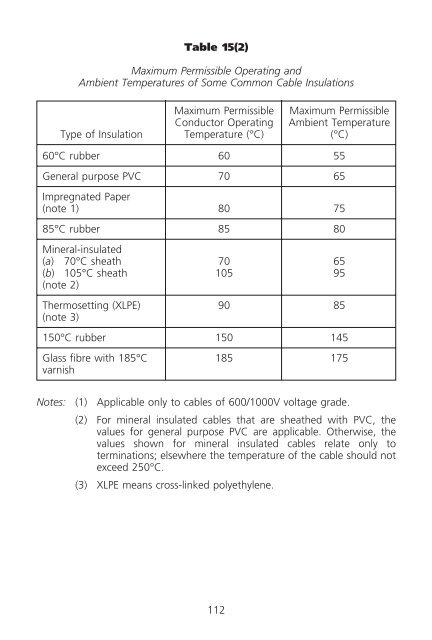
- Page 105 and 106: Code 15 ADVERSE CONDITIONS INSTALLA
- Page 107 and 108: (c) Where cables are to be connecte
- Page 109 and 110: (d ) Electrical equipment and wirin
- Page 111: (b) There should be adequate means
- Page 115 and 116: Table 15(5) Relationship between T
- Page 117 and 118: Code 16 OVERHEAD LINE INSTALLATIONS
- Page 119 and 120: 16I Earthing of Metallic Parts and
- Page 123 and 124: Code 18 ALTERATIONS AND ADDITIONS 1
- Page 125 and 126: Code 19 FIRST INSPECTION, TESTING A
- Page 127 and 128: (d ) Every certificate should be si
- Page 129 and 130: Code 20 PERIODIC INSPECTION, TESTIN
- Page 131 and 132: (f ) premises that the Director may
- Page 133 and 134: Code 21 PROCEDURES FOR INSPECTION,
- Page 135 and 136: (5) Insulation resistance (a) A sui
- Page 137 and 138: (8) Earth fault loop impedance (a)
- Page 139 and 140: 21D Testing of High Voltage Install
- Page 141 and 142: Table 21(1) Minimum Values of Insul
- Page 143 and 144: 143
- Page 145 and 146: 145
- Page 147 and 148: 147
- Page 149 and 150: Code 22 MAKING AND KEEPING OF RECOR
- Page 151 and 152: and testing results are also proper
- Page 153 and 154: PART II Code 25 GENERAL WORKMANSHIP
- Page 155 and 156: (i) Adjacent or parallel conduits c
- Page 157 and 158: (b) Where cables run as a span betw
- Page 159 and 160: (b) Unless otherwise advised by the
- Page 161 and 162: procedure adopted should be as reco
- Page 163 and 164:
(b) For steel surface conduit insta
- Page 165 and 166:
165
- Page 167 and 168:
167
- Page 169 and 170:
26I Lightning Protection Installati
- Page 171 and 172:
(3) Electrical equipment in bathroo
- Page 173 and 174:
(b) Fixed air-conditioners and spac
- Page 175 and 176:
(d ) Single phase domestic thermal
- Page 177 and 178:
(b) Where protective devices are us
- Page 179 and 180:
26E Supply Connection to Welding Se
- Page 181 and 182:
exterior installation and a tempora
- Page 183 and 184:
26I Lightning Protection Installati
- Page 185 and 186:
(v) Where wooden poles are used, al
- Page 187 and 188:
(c) Zone 3 is the volume outside Zo
- Page 189 and 190:
Zone 2 is limited by: (a) the verti
- Page 191 and 192:
• SELV, the source of SELV being
- Page 193 and 194:
• The height from the floor is at
- Page 195 and 196:
(f ) Every safety source and isolat
- Page 197 and 198:
circuits are electrically separated
- Page 199 and 200:
(b) Protection against earth leakag
- Page 201 and 202:
201
- Page 203 and 204:
203
- Page 205 and 206:
205
- Page 207 and 208:
207
- Page 209 and 210:
Appendix 1 Prescribed Requirements
- Page 211 and 212:
( j) Multiple socket outlets should
- Page 213 and 214:
(8) Marking (a) The socket outlet s
- Page 215 and 216:
215
- Page 217 and 218:
Appendix 2 Prescribed Requirements
- Page 219 and 220:
etween the base and the inside wall
- Page 221 and 222:
(c) The letters L and N should be u
- Page 223 and 224:
223
- Page 225 and 226:
225
- Page 227 and 228:
(e) Conductive component parts of s
- Page 229 and 230:
(b) All accessible metal parts at a
- Page 231 and 232:
231
- Page 233 and 234:
233
- Page 235 and 236:
235
- Page 237 and 238:
(f ) (i) Socket outlets having a ra
- Page 239 and 240:
material from current carrying part
- Page 241 and 242:
241
- Page 243 and 244:
243
- Page 245 and 246:
245
- Page 247 and 248:
247
- Page 249 and 250:
249
- Page 251 and 252:
251
- Page 253 and 254:
(2) Correction factors for groups o
- Page 255 and 256:
(5) Correction factors for cables i
- Page 257 and 258:
This page is intentionally left bla
- Page 259 and 260:
TABLE A6(1) (Cont.) VOLTAGE DROP (p
- Page 261 and 262:
TABLE A6(2) (Cont.) VOLTAGE DROP (p
- Page 263 and 264:
TABLE A6(3) (Cont.) VOLTAGE DROP (p
- Page 265 and 266:
TABLE A6(4) (Cont.) VOLTAGE DROP (p
- Page 267 and 268:
TABLE A6(5) (Cont.) VOLTAGE DROP (p
- Page 269 and 270:
TABLE A6(6) (Cont.) VOLTAGE DROP (p
- Page 271 and 272:
TABLE A6(7) (Cont.) VOLTAGE DROP (p
- Page 273 and 274:
TABLE A6(8) (Cont.) VOLTAGE DROP (p
- Page 275 and 276:
275
- Page 277 and 278:
277
- Page 279 and 280:
Appendix 8 Graphical Symbols for El
- Page 281 and 282:
281
- Page 283 and 284:
No. Symbol Description 35. 36. 37.
- Page 285 and 286:
No. Symbol Description 56. 57. 58.
- Page 287 and 288:
Appendix 9 Performance Monitoring P
- Page 289 and 290:
(Note: The information above is ext
- Page 291 and 292:
(Note: The information above is ext
- Page 294:
(c) 4 mm 2 PVC insulated copper cab
- Page 297 and 298:
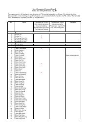
Appendix 13 B) Checklists (Note: Fo
- Page 299:
(v) All exposed metal parts includi
- Page 304 and 305:
(xiv) Suitable cable terminations p
- Page 306 and 307:
(f ) Final circuits (i) All fuses a
- Page 308 and 309:
Tested by/Date (N/A if not applicab
- Page 310 and 311:
(x) No evidence of corrosion likely
- Page 313 and 314:
Appendix 14 References References m
- Page 315 and 316:
BS EN 60598 Luminaires BS EN 60669
- Page 317 and 318:
BS 6004 Electric cables. PVC insula
- Page 319 and 320:
Appendix 15 Safety for Live Work (A
- Page 325 and 326:
Appendix 18 New Cable Colour Code f
- Page 327 and 328:
Figure A18(2b) - New coloured wirin
- Page 329 and 330:
. Existing cables adopting either y
- Page 331 and 332:
INDEX Alterations and additions to
- Page 333 and 334:
final 4G(3), 6B(1)(b), 6B(4), 6C(c)
- Page 335 and 336:
Final circuits arrangement ring sep
- Page 337 and 338:
Overcurrent protective device coord