Double insulation Duct Earth fault current Earth-free local equipotential bonding Ear<strong>the</strong>d equipotential bonding Electrical equipment, safety requirement Emergency switch Equipotential bonding Equipotential zone Exhibitions, shows and stands Explosive atmosphere Exposed conductive parts Extraneous conductive parts bathroom bonding <strong>of</strong> swimming pools Fault Fault protection FELV Festive lighting 5A(b), 11D(1), 11D(2) 2, 5B(2)(b), 5B(3)(b), 5C(a), Table 5(1), 13A(2)(h), 14A(3), 15A(2)(h), 15B(4)(b), 15E(c) 2, 11, 11J, 12B(3), 18A(b) 26L(3)(b) 11A 4, 15D, Table 15(4) 8A(3), 8A(6), 8B(1)(c), 8B(4), 26H(3) 2, 4C(2)(c), 11A, 11B(b), 11C, 11E, 11F, 21B(2)(a), 21B(4), 25D(8)(a), 26A(3), 26L(3)(b), 26M(3), 26M(5)(d ), 26N(4), 26Q(3)(b) 11B(b), 11E, 11F(a) 26Q 4B(2)(b), 15D(1)(a), 15D(2)(c) 2, 4C(2)(c), 11A, 11B, 11D, 11F, 12B(2), 14D(2)(b), 21B(6)( f ), 21C(b), 25D(5)(a), 25D(8)(a), 26A(3), 26E, 26H(7), 26M(3), 26N(4) 11B(b), 26A(3) 4C(2)(c), 11E(a), 11F, 21B(4), 25D(8)(a), 26(3)(b), 26M(3), 26N(4)(c) 26M(3) 2, 6B(1), 8A(1), 9A(1), 9A(3), 9B(2), 9C(1), 9C(2), 9D(3), Table 9(2), Table 9(3), 11A, 11B, 11I, 11J, Table 11(5), Table 11(8), Table 11(9), Table 11(10), Table 11(11), Table 11(12), Table 11(13), Table 11(14), 13A(1), 18A(b), 21B(2), 21B(8), 21B(9), 21B(10), 26A(3)(a), 26H(5), 26K 2, 11A, 11J(2)(c), 21A(o), 26N(2), 26N(4) 26N(2) 26Q 334
Final circuits arrangement ring separation <strong>of</strong> joint Fire barriers Fuse Generator Harmonic current High voltage discharge lighting Inspection and testing Instantaneous water heater Insulation Isolation motor circuit neutral conductor plug and socket outlet remote devices requirement Joints cable and conductor conduit system earthing system 4G(3), 6B(1)(b), 6C, 6D, 6E, 6F, 6G, 6H, Table 6(1), 7B(3), 7B(4), Table 7(1), 26A(4)(a) 6C, 6E, 6F, Table 6(1), 11D(3)(d ), 21B(4) 6B(4) 25D(1) 14A(3), 21A( f ) 2, 4D(1)(a), 4E(d ), 6D(b), 6E(2), 6E(4), 6F, 6G, Table 6(1), 8B(2)(b), 9A(2), 9B(1)(d ), 9E, Table 9(2), 10A(b), 10B, Table 11(3), Table 11(4), Table 11(8), Table 11(9), Table 11(11), Table 11(12), 13A(4)(d ), 21A(j), 21B(5)(c), 21B(6)(a), 21B(9)(b), 21B(10)(d ), 26A(4)(a), 26A(5), 26A(6)(e) 8A(1)(d ), 10C, 26K(3)( f ), 26N(4)( f ), 26Q(3)( f ) 4D(3), 6B(6)(c), 7B(3)(b), 26H(1)(b) 8A(2)(b), 8B(4)(d ), 20A(3)(b), 26H 4D(3), 22D(1), 22D, 26K(2)(b), 26P(3) Table 7(1), 26A(5) 4C(1)(c), 9B(1)(a), Table 9(1), 13A(3), 13A(4)(e), 13B(1), 14E(2)(d ), 15A(2), 15B(2), 15B(3), 15B(5)(b), 15G(a), Table 15(1), Table 15(2), 21A(g), 21B(2)(a), 21B(5), 21B(10)(a), 21E(2), Table 21(1), 25D(3)(b), 26H(5)(a), 26L(5)(c), 26N(2)(b) 8A(3), 8A(4) 6B(6), 8A(1)(a), 8B(2)(a), 10A(b), 26D(b), 26H(3)(a) 8A(2)(a), 26A(5)(c), 26O(c) 8A(4)(a) 4C(2)(c), 6B(2), 8A, 8A(2), 8B, 21H(2), 26Q(3)(e) 13C(b), 13C(g), 15B(3)(a), 25D 25A(1)(a), 25A(2)(a), 25A(3)(b) 11H(d ) 335
- Page 2 and 3:
CODE OF PRACTICE FOR THE ELECTRICIT
- Page 4 and 5:
Page 6G Final Circuits Using 16A In
- Page 6 and 7:
Page 17. Display of Labels and Noti
- Page 8 and 9:
Page Appendices 208 1. Prescribed R
- Page 10 and 11:
Code 1 INTRODUCTION PART I This Cod
- Page 12 and 13:
‘cable trunking’ means a manufa
- Page 14 and 15:
‘powertrack system’ means an as
- Page 16 and 17:
Code 3 APPLICATION 3A General Appli
- Page 18 and 19:
Code 4 GENERAL SAFETY REQUIREMENTS
- Page 20 and 21:
warning notices and the placing of
- Page 22 and 23:
4E Working Space (a) A minimum clea
- Page 24 and 25:
Additional lighting should be provi
- Page 26 and 27:
(b) Work procedure for High Voltage
- Page 28 and 29:
(ii) Keep hands away from any circu
- Page 30 and 31:
Code 5 SEGREGATION OF CIRCUIT CATEG
- Page 32 and 33:
(i) A minimum horizontal or vertica
- Page 34 and 35:
Code 6 CIRCUIT ARRANGEMENT 6A Divis
- Page 36 and 37:
(2) Control Each circuit should be
- Page 38 and 39:
(4) Permanently connected equipment
- Page 40:
Type of Circuit A1 Ring A2 Radial A
- Page 47 and 48:
Code 7 CURRENT DEMAND 7A Current De
- Page 49 and 50:
Purpose of Conductors or Switchgear
- Page 51 and 52:
Code 8 ISOLATION AND SWITCHING 8A P
- Page 53 and 54:
(iv) luminaires (lamp replacement a
- Page 55:
(3) Devices for switching off for m
- Page 58 and 59:
Code 9 OVERCURRENT PROTECTIVE DEVIC
- Page 60 and 61:
Overload protective devices may hav
- Page 62 and 63:
Table 9(1) Limiting Final Temperatu
- Page 64 and 65:
Table 9(4) Classification of MCB to
- Page 66 and 67:
Code 10 NEUTRAL CONDUCTOR PROTECTIV
- Page 68 and 69:
Code 11 EARTH LEAKAGE AND EARTH FAU
- Page 70 and 71:
(b) Subject to subparagraph (a) abo
- Page 72:
(Note: 1. An extraneous conductive
- Page 76 and 77:
(d ) Where a residual current devic
- Page 78 and 79:
(c) Values of k for protective cond
- Page 80 and 81:
Table 11(4) Minimum Cross-sectional
- Page 82:
Table 11(11) Maximum Earth Fault Lo
- Page 85 and 86:
Code 12 EARTHING ARRANGEMENT 12A Ge
- Page 87 and 88:
(4) Plate electrode Plate electrode
- Page 89 and 90:
Code 13 CONDUCTORS, JOINTS AND CONN
- Page 91 and 92:
(a) the ambient temperature does no
- Page 93 and 94:
(2) Identification of cable cores (
- Page 95 and 96:
Code 14 WIRING INSTALLATION ENCLOSU
- Page 97 and 98:
(b) Flexible steel conduits should
- Page 99 and 100:
14E Cable Capacity of Enclosures (1
- Page 101 and 102:
Table 14(2) Cable Factors and Condu
- Page 103 and 104:
Table 14(4) Cable Factors and Trunk
- Page 105 and 106:
Code 15 ADVERSE CONDITIONS INSTALLA
- Page 107 and 108:
(c) Where cables are to be connecte
- Page 109 and 110:
(d ) Electrical equipment and wirin
- Page 111 and 112:
(b) There should be adequate means
- Page 114 and 115:
Table 15(4) Selection of Electrical
- Page 116 and 117:
Code 16 OVERHEAD LINE INSTALLATIONS
- Page 118 and 119:
(2) Any point of the span The condu
- Page 120:
Code 17 DISPLAY OF LABELS AND NOTIC
- Page 124 and 125:
Code 18 ALTERATIONS AND ADDITIONS 1
- Page 126 and 127:
Code 19 FIRST INSPECTION, TESTING A
- Page 128 and 129:
Code 20 PERIODIC INSPECTION, TESTIN
- Page 130 and 131:
(b) Examples of the above are dange
- Page 132 and 133:
Code 21 PROCEDURES FOR INSPECTION,
- Page 134 and 135:
21B Testing of Low Voltage Installa
- Page 136 and 137:
(6) Polarity (a) A test of polarity
- Page 138 and 139:
(d ) Secondary Injection Test (i) T
- Page 140 and 141:
will have affected the results of t
- Page 142 and 143:
142
- Page 144 and 145:
144
- Page 146 and 147:
146
- Page 148 and 149:
Code 22 MAKING AND KEEPING OF RECOR
- Page 150 and 151:
Checklists Requirements to be Used
- Page 152 and 153:
Code 23 & Code 24 (Reserved for Fut
- Page 154 and 155:
Part II Code 25 GENERAL WORKMANSHIP
- Page 156 and 157:
equipment should be suitable for th
- Page 158 and 159:
(2) Installation of PVC insulated,
- Page 160 and 161:
(c) Where cold compound with plasti
- Page 162 and 163:
(b) Earth continuity across joints
- Page 164 and 165:
Table 25(2) Spacing of Supports for
- Page 166 and 167:
166
- Page 168 and 169:
Code 26 REQUIREMENTS FOR SPECIFIC I
- Page 170 and 171:
Code 26 REQUIREMENTS FOR SPECIFIC I
- Page 172 and 173:
(iii) controls and switches of wate
- Page 174 and 175:
(vi) Except as provided by (vii) wh
- Page 176 and 177:
(b) Facilities should be incorporat
- Page 178 and 179:
(3) Starting facilities of electric
- Page 180 and 181:
than the product of the total stead
- Page 182 and 183:
(5) Transformers (a) Every transfor
- Page 184 and 185:
(b) Electrical apparatus and wiring
- Page 186 and 187:
(f ) Supply from generator set Wher
- Page 188 and 189:
manufacturer’s instructions. Othe
- Page 190 and 191:
• SELV, the source for SELV being
- Page 192 and 193:
protected by an RCD having the char
- Page 194 and 195:
(2) Basic protection and fault prot
- Page 196 and 197:
plug. The permanent connection to t
- Page 198 and 199:
prevent electric shock to electrica
- Page 200 and 201:
Table 26(1) Recommended Number of S
- Page 202 and 203:
202
- Page 204 and 205:
204
- Page 206 and 207:
206
- Page 208 and 209:
APPENDICES 1. Prescribed Requiremen
- Page 210 and 211:
(d ) The spacing of the socket cont
- Page 212 and 213:
diameter of the clamping screw and
- Page 214 and 215:
214
- Page 216 and 217:
216
- Page 218 and 219:
contact with appropriate socket con
- Page 220 and 221:
(ii) between live parts and any oth
- Page 222 and 223:
222
- Page 224 and 225:
224
- Page 226 and 227:
(1) General Appendix 3 Prescribed R
- Page 228 and 229:
(d ) An earthing terminal should be
- Page 230 and 231:
230
- Page 232 and 233:
232
- Page 234 and 235:
234
- Page 236 and 237:
Appendix 4 Prescribed Requirements
- Page 238 and 239:
(5) Screws and connections (a) Scre
- Page 240 and 241:
240
- Page 242 and 243:
242
- Page 244 and 245:
244
- Page 246 and 247:
246
- Page 248 and 249:
248
- Page 250 and 251:
250
- Page 252 and 253:
Appendix 5 Correction Factors for S
- Page 254 and 255:
(3) Correction factors for cables e
- Page 256 and 257:
Appendix 6 Current Carrying Capacit
- Page 258 and 259:
TABLE A6(1) Single-core PVC insulat
- Page 260 and 261:
TABLE A6(2) Multicore PVC insulated
- Page 262 and 263:
TABLE A6(3) Single-core armoured PV
- Page 264 and 265:
TABLE A6(4) Multicore armoured PVC
- Page 266 and 267:
TABLE A6(5) Single core XLPE insula
- Page 268 and 269:
TABLE A6(6) Multicore XLPE insulate
- Page 270 and 271:
TABLE A6(7) Single-core XLPE insula
- Page 272 and 273:
TABLE A6(8) Multicore armoured XLPE
- Page 274 and 275:
274
- Page 276 and 277:
276
- Page 278 and 279:
278
- Page 280 and 281:
280 Contactor Main make contact of
- Page 282 and 283:
282 Junction, connection point
- Page 284 and 285: No. Symbol Description 45. 46. 47.
- Page 286 and 287: No. Symbol Description 68. 69. 70.
- Page 288 and 289: Appendix 10 Degree of Protection Pr
- Page 290 and 291: Appendix 11 Forms of Internal Separ
- Page 292: Appendix 12 Worked Examples for App
- Page 296 and 297: Appendix 13 A) Schedule of Test Res
- Page 298 and 299: (iii) All joints of metal conduit o
- Page 303 and 304: Checklist No. 4—Additional Items
- Page 305 and 306: (iv) Suitable stay wires installed
- Page 307 and 308: Tested by/Date (N/A if not applicab
- Page 309 and 310: (vii) Protective conductor up to an
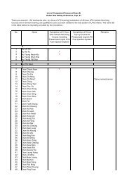
- Page 311: Checklist No. 5—Items for H.V. In
- Page 314 and 315: IEC 60947 Low-voltage switchgear an
- Page 316 and 317: BS 88 Part 6 Cartridge fuses for vo
- Page 318 and 319: References may be made to the follo
- Page 320: 320
- Page 326 and 327: (3) Precautions In the new colour c
- Page 328 and 329: 5.2 Single-phase installation Exten
- Page 330 and 331: 5.3 Three-phase installation Extens
- Page 332 and 333: enclosure in conduit and trunking i
- Page 336 and 337: Joints and termination Labels bondi
- Page 338: Socket outlets general installation