The Development of Neural Network Based System Identification ...
The Development of Neural Network Based System Identification ...
The Development of Neural Network Based System Identification ...

Create successful ePaper yourself
Turn your PDF publications into a flip-book with our unique Google optimized e-Paper software.
4.3 SYSTEM IDENTIFICATION WITH NEURAL NETWORK 91<br />
• Frequency swept excitation<br />
signals<br />
• DC and <strong>of</strong>fset removal<br />
• Digital filter with 10Hz cut-<strong>of</strong>f<br />
frequency<br />
• Sampling frequency = 50Hz<br />
• Multilayer Perceptron <strong>Network</strong><br />
(MLP) based on ARX model<br />
• Choose lag space using Lipschitz<br />
coefficient<br />
• Determine number <strong>of</strong> neurons<br />
which guarantee minimum FPE<br />
error (generalization ability to<br />
new data)<br />
• Minimization <strong>of</strong> the criterion<br />
was done using the Levenberg-<br />
Marquardt (LM) optimization<br />
algorithm with regularization<br />
Test Data<br />
Gathering<br />
Process<br />
NN Model<br />
Structure<br />
Selection<br />
Model<br />
Estimation<br />
Validation<br />
Process<br />
• One-step ahead prediction<br />
• k-step ahead prediction<br />
• k-fold cross validation<br />
Accept for<br />
Use?<br />
No<br />
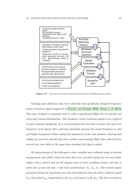
Figure 4.7<br />
Overview <strong>of</strong> neural network based system identification procedure.<br />
Training and validation data were collected from specifically designed frequency<br />
swept excitation signal suggested in Tischler and Remple [2006], Wang et al. [2011].<br />
This type <strong>of</strong> signal is commonly used to collect experimental flight data in aircraft and<br />
rotorcraft system identification. <strong>The</strong> frequency swept excitation signal is not required<br />
to have constant amplitude. It is recommended that the pilot executes two good low<br />
frequency cycle inputs (20 s) and then gradually increase the swept frequency to mid<br />
and higher frequencies before ending the manoeuvre in the trim position. Starting and<br />
ending the record in aircraft trim state enables concatenating flight data collected from<br />
several test runs while at the same time ensuring rich signal content.<br />
All measurements <strong>of</strong> the helicopter’s state variables were collected using an inertial<br />
measurement unit (IMU) where the data that were recorded during the test were Euler<br />
angles: roll φ, pitch θ and yaw Ψ; angular rates in body coordinate frame: roll rate, p,<br />
pitch rate, q and yaw rate, r and body accelerations: A x , A y , A z . <strong>The</strong> control inputs<br />
measured during the experiment were the stick deflection from the pilot’s collective pitch<br />
δ col , tail pedal δ ped , longitudinal cyclic δ lon and lateral cyclic δ lat . <strong>The</strong> four servomotor