The Development of Neural Network Based System Identification ...
The Development of Neural Network Based System Identification ...
The Development of Neural Network Based System Identification ...

You also want an ePaper? Increase the reach of your titles
YUMPU automatically turns print PDFs into web optimized ePapers that Google loves.
3.2 AIR VEHICLE DESCRIPTIONS 61<br />
up and down along the main rotor shaft.<br />
A total <strong>of</strong> three electrically powered Futaba S9252 and one JR 8900G actuators<br />
or control servos are used to position collective, lateral cyclic, longitudinal cyclic and<br />
tail rotor linkages. <strong>The</strong> rotation speed <strong>of</strong> the brushless DC motor is controlled through<br />
an electronic speed controller (ESC). A small rechargeable 4.8 V Type C 2000 mA h<br />
battery provides power to the actuators through a 2.4 GHz AR7000 Remote Control<br />
(RC) receiver located in the servo mounting frame. <strong>The</strong> receiver processes signals<br />
transmitted by a hand-held Spektrum DX7 transmitter on the ground and produces<br />
Pulse Width Modulated (PWM) output signals to drive the servos.<br />
<strong>The</strong> AR7000<br />
receiver combines an internal and external receiver, which <strong>of</strong>fers superior performance<br />
in comparison with conventional narrow band systems. <strong>The</strong> Spektrum radio system<br />
simultaneously transmits two frequencies which create dual RF paths, and this virtually<br />
makes the system immune to internal and external radio interference. <strong>The</strong> receiver<br />
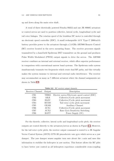
may accommodate as many as 7 different actuators where the channel assignments are<br />
shown in Table 3.2.<br />
Table 3.2<br />
RC receiver output channels<br />
Receiver Channel Output Description<br />
CH1 THRO Electric motor/Electronic speed control (ESC)<br />
CH2 AILE Collective/Cyclic pitch movement<br />
CH3 ELEV Collective/Cyclic pitch movement<br />
CH4 RUDD Tail rotor cyclic pitch movement<br />
CH5 GEAR Auxiliary Channel<br />
CH6 AUX1 Collective/Cyclic pitch movement<br />
CH7 AUX2 Rate Gyro Sensitivity Switching<br />
CH8 BATT Power Supply (5V)<br />
For the throttle, collective, lateral cyclic and longitudinal cyclic pitch, the receiver<br />
outputs are routed directly to the actuators/servos as shown in Figure 3.5. However,<br />
for the tail rotor cyclic pitch, the receiver output command is routed to a JR Angular<br />
Vector Control <strong>System</strong> (AVCS) G770 3D piezoelectric rate gyro which serves as a yaw<br />
damper. <strong>The</strong> yaw damper senses angular turn rate about the z-axis and uses this<br />
information to stabilise the helicopter in yaw motion. This feature allows the RC pilot<br />
to have better yaw control as all helicopters experience considerable cross-coupling