The Development of Neural Network Based System Identification ...
The Development of Neural Network Based System Identification ...
The Development of Neural Network Based System Identification ...

Create successful ePaper yourself
Turn your PDF publications into a flip-book with our unique Google optimized e-Paper software.
22 CHAPTER 2 LITERATURE REVIEW<br />
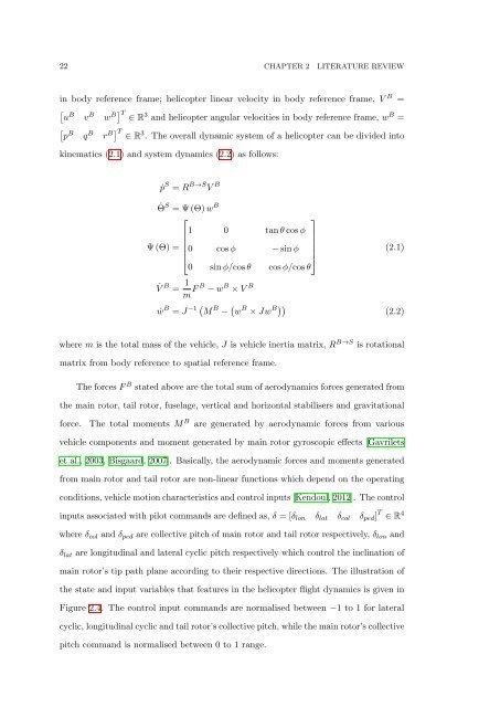
in body reference frame; helicopter linear velocity in body reference frame, V B =<br />
[<br />
u B v B w B] T ∈ R 3 and helicopter angular velocities in body reference frame, w B =<br />
[<br />
p B q B r B] T ∈ R 3 . <strong>The</strong> overall dynamic system <strong>of</strong> a helicopter can be divided into<br />
kinematics (2.1) and system dynamics (2.2) as follows:<br />
ṗ S = R B→S V B<br />
˙Θ S = Ψ (Θ) w B<br />
⎡<br />
⎤<br />
1 0 tan θ cos φ<br />
Ψ (Θ) =<br />
⎢0 cos φ − sin φ<br />
⎥<br />
⎣<br />
⎦<br />
0 sin φ/cos θ cos φ/cos θ<br />
(2.1)<br />
˙V B = 1 m F B − w B × V B<br />
ẇ B = J −1 ( M B − ( w B × Jw B)) (2.2)<br />
where m is the total mass <strong>of</strong> the vehicle, J is vehicle inertia matrix, R B→S is rotational<br />
matrix from body reference to spatial reference frame.<br />
<strong>The</strong> forces F B stated above are the total sum <strong>of</strong> aerodynamics forces generated from<br />
the main rotor, tail rotor, fuselage, vertical and horizontal stabilisers and gravitational<br />
force.<br />
<strong>The</strong> total moments M B are generated by aerodynamic forces from various<br />
vehicle components and moment generated by main rotor gyroscopic effects [Gavrilets<br />
et al., 2003, Bisgaard, 2007]. Basically, the aerodynamic forces and moments generated<br />
from main rotor and tail rotor are non-linear functions which depend on the operating<br />
conditions, vehicle motion characteristics and control inputs [Kendoul, 2012]. <strong>The</strong> control<br />
inputs associated with pilot commands are defined as, δ = [δ lon δ lat δ col δ ped ] T ∈ R 4<br />
where δ col and δ ped are collective pitch <strong>of</strong> main rotor and tail rotor respectively, δ lon and<br />
δ lat are longitudinal and lateral cyclic pitch respectively which control the inclination <strong>of</strong><br />
main rotor’s tip path plane according to their respective directions. <strong>The</strong> illustration <strong>of</strong><br />
the state and input variables that features in the helicopter flight dynamics is given in<br />
Figure 2.4. <strong>The</strong> control input commands are normalised between −1 to 1 for lateral<br />
cyclic, longitudinal cyclic and tail rotor’s collective pitch, while the main rotor’s collective<br />
pitch command is normalised between 0 to 1 range.