The Development of Neural Network Based System Identification ...
The Development of Neural Network Based System Identification ...
The Development of Neural Network Based System Identification ...

Create successful ePaper yourself
Turn your PDF publications into a flip-book with our unique Google optimized e-Paper software.
190 CHAPTER 7 FLIGHT CONTROL SYSTEM DESIGN: RESULTS AND DISCUSSION<br />
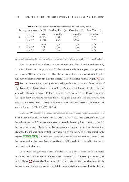
Table 7.3<br />
<strong>The</strong> control performance comparison with various r w values.<br />
Tuning parameter MSE Settling Time (s) Overshoot (%) Rise Time (s)<br />
θ<br />
φ<br />
r w = 1.0 1.9219 unstable unstable unstable<br />
r w = 1.5 0.1934 1.32 23.02 0.36<br />
r w = 2.0 0.1975 3.80 47.45 0.59<br />
r w = 1.0 10.26 n/a n/a n/a<br />
r w = 1.5 0.07 n/a n/a n/a<br />
r w = 2.0 0.75 n/a n/a n/a<br />
action is penalised too much in the cost function resulting in higher overshoot value.<br />
Next, the controllers’ performance is tested under the effect <strong>of</strong> prediction horizon N p<br />
variation. <strong>The</strong> experiment procedures for this test are similar to the previous experiment<br />
procedures. <strong>The</strong> only difference is that the test is performed under active roll, pitch<br />
and yaw controllers while the altitude channel is under manual control. Figure 7.3 and<br />
7.4 show the results for comparing the controller performances under different values <strong>of</strong><br />
N p . Both <strong>of</strong> the figures show the controller performance results for roll, pitch and yaw<br />
channels. <strong>The</strong> control penalty factor <strong>of</strong> r w = 1.5 is used in each <strong>of</strong> MPC controller setup.<br />
<strong>The</strong> same input constraints are used for roll and pitch controller as in the previous test,<br />
whereas, the constraint on the yaw rate controller is set up based on the rate <strong>of</strong> the<br />
control input, −0.015 ≤ ∆u(k) ≤ 0.015.<br />
Since the RC helicopter dynamics is unstable, several stability augmentation devices<br />
such as the mechanical stabiliser bar and active yaw rate feedback controller have been<br />
introduced to the RC helicopter system to enable human pilots to control the RC<br />
helicopter with ease. <strong>The</strong> stabiliser bar acts as a rate lagged feedback mechanism that<br />
dampens the roll and pitch control sensitivity due to the lateral and longitudinal cyclic<br />
inputs [Mettler, 2003]. <strong>The</strong> feedback mechanism would ease the manual control <strong>of</strong> the<br />
helicopter and at the same time reduce the destabilising effect on the helicopter due to<br />
wind gust or turbulence.<br />
In addition, the yaw rate feedback controller and a gyro sensor are also included<br />
in all RC helicopter models to improve the stabilisation <strong>of</strong> the helicopter in the yaw<br />
axis. Figure 7.5 shows the illustration <strong>of</strong> the link between the yaw dynamics <strong>of</strong> the<br />
helicopter and the component <strong>of</strong> the stability augmentation systems. Ideally, the yaw