The Development of Neural Network Based System Identification ...
The Development of Neural Network Based System Identification ...
The Development of Neural Network Based System Identification ...

You also want an ePaper? Increase the reach of your titles
YUMPU automatically turns print PDFs into web optimized ePapers that Google loves.
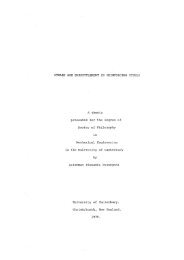
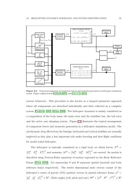
2.2 HELICOPTER DYNAMICS MODELLING AND SYSTEM IDENTIFICATION 21<br />
Flight Control<br />
<strong>System</strong><br />
Summation<br />
<strong>of</strong> Forces,<br />
Inertial Translational Velocities<br />
u, v, w<br />
Atmospheric<br />
Motion<br />
+<br />
Main Rotor &<br />
Stabiliser Bar<br />
Tail Rotor<br />
Kinematics<br />
Gravity<br />
Components<br />
Euler<br />
Angles<br />
Fuselage<br />
Engine/<br />
Transmission<br />
Summation <strong>of</strong><br />
Moments,<br />
Inertial Rotational Velocities<br />
p, q, r<br />
Atmospheric<br />
Motion<br />
+<br />
Empennage<br />
Figure 2.3 Typical arrangement <strong>of</strong> component forces and moments generation in helicopter simulation<br />
model. Figure adapted from Padfield [2007] and Cai et al. [2013].<br />
system behaviour. This procedure is also known as a lumped parameter approach<br />
where all components are described individually and then collected as a complete<br />
system [Padfield, 2007, Shim, 2000]. <strong>The</strong> helicopter dynamics is mainly considered as<br />
a composition <strong>of</strong> the body mass, the main rotor and the stabiliser bar, the tail rotor<br />
and the active yaw damping system. Figure 2.3 illustrates the typical arrangement<br />
<strong>of</strong> component forces and moments generation in a helicopter simulation model. <strong>The</strong><br />
aerodynamic drag effects from the fuselage, horizontal and vertical stabiliser are normally<br />
neglected as they play a less important role under hovering and slow flight conditions<br />
for model scaled helicopter.<br />
<strong>The</strong> helicopter is basically considered as a rigid body on which forces, F B =<br />
[<br />
F<br />
B<br />
x F B y F B z<br />
] T and moments, M B = [ M B x M B y M B z<br />
] T are exerted. Its motion is<br />
described using Newton-Euler equations <strong>of</strong> motion expressed in the Body Reference<br />
Frame [Shim, 2000]. Let superscript S and B represent spatial (inertial) and body<br />
reference frame respectively.<br />
<strong>The</strong> twelve dimensional state vectors consist <strong>of</strong> the<br />
helicopter’s centre <strong>of</strong> gravity (CG) position vectors in spatial reference frame, p S =<br />
[<br />
p<br />
S<br />
x p S y p S ] T<br />
z ∈ R 3 ; Euler angles (roll, pitch and yaw), Θ B = [ φ B θ B ψ B] T ∈ R<br />
3