The Development of Neural Network Based System Identification ...
The Development of Neural Network Based System Identification ...
The Development of Neural Network Based System Identification ...

You also want an ePaper? Increase the reach of your titles
YUMPU automatically turns print PDFs into web optimized ePapers that Google loves.
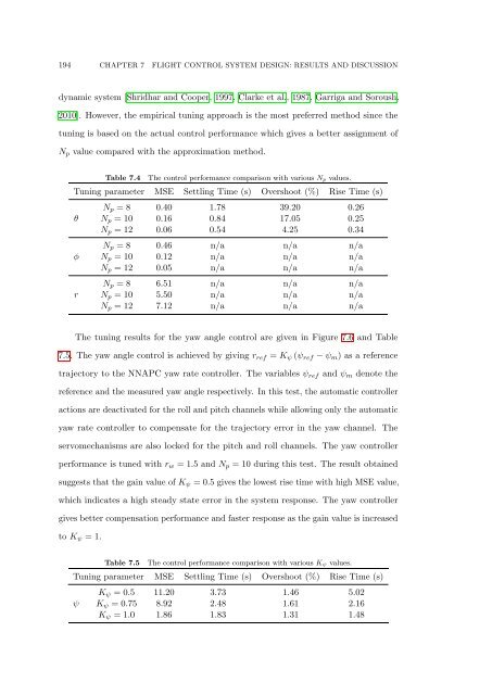
194 CHAPTER 7 FLIGHT CONTROL SYSTEM DESIGN: RESULTS AND DISCUSSION<br />
dynamic system [Shridhar and Cooper, 1997, Clarke et al., 1987, Garriga and Soroush,<br />
2010]. However, the empirical tuning approach is the most preferred method since the<br />
tuning is based on the actual control performance which gives a better assignment <strong>of</strong><br />
N p value compared with the approximation method.<br />
Table 7.4<br />
<strong>The</strong> control performance comparison with various N p values.<br />
Tuning parameter MSE Settling Time (s) Overshoot (%) Rise Time (s)<br />
θ<br />
φ<br />
r<br />
N p = 8 0.40 1.78 39.20 0.26<br />
N p = 10 0.16 0.84 17.05 0.25<br />
N p = 12 0.06 0.54 4.25 0.34<br />
N p = 8 0.46 n/a n/a n/a<br />
N p = 10 0.12 n/a n/a n/a<br />
N p = 12 0.05 n/a n/a n/a<br />
N p = 8 6.51 n/a n/a n/a<br />
N p = 10 5.50 n/a n/a n/a<br />
N p = 12 7.12 n/a n/a n/a<br />
<strong>The</strong> tuning results for the yaw angle control are given in Figure 7.6 and Table<br />
7.5. <strong>The</strong> yaw angle control is achieved by giving r ref = K ψ (ψ ref − ψ m ) as a reference<br />
trajectory to the NNAPC yaw rate controller. <strong>The</strong> variables ψ ref and ψ m denote the<br />
reference and the measured yaw angle respectively. In this test, the automatic controller<br />
actions are deactivated for the roll and pitch channels while allowing only the automatic<br />
yaw rate controller to compensate for the trajectory error in the yaw channel. <strong>The</strong><br />
servomechanisms are also locked for the pitch and roll channels. <strong>The</strong> yaw controller<br />
performance is tuned with r w = 1.5 and N p = 10 during this test. <strong>The</strong> result obtained<br />
suggests that the gain value <strong>of</strong> K ψ = 0.5 gives the lowest rise time with high MSE value,<br />
which indicates a high steady state error in the system response. <strong>The</strong> yaw controller<br />
gives better compensation performance and faster response as the gain value is increased<br />
to K ψ = 1.<br />
Table 7.5<br />
<strong>The</strong> control performance comparison with various K ψ values.<br />
Tuning parameter MSE Settling Time (s) Overshoot (%) Rise Time (s)<br />
ψ<br />
K ψ = 0.5 11.20 3.73 1.46 5.02<br />
K ψ = 0.75 8.92 2.48 1.61 2.16<br />
K ψ = 1.0 1.86 1.83 1.31 1.48