- Page 1 and 2:
Con v e r t i n g Wa s t e Agr i c
- Page 3 and 4:
Converting Waste Agricultural Bioma
- Page 5 and 6:
setting and identification of stake
- Page 7 and 8:
ACRONYMS CO2 CV DAP DTIE ESTs E-Was
- Page 9 and 10:
2. Rationale One of the critical ac
- Page 11 and 12:
3. Scope and Limitations In compili
- Page 13 and 14:
4. The Compendium The Project Websi
- Page 15 and 16:
• Basic technology information 9
- Page 17 and 18:
Table 1: Cellulosic Waste Biomass C
- Page 19 and 20:
Molding Oil Palm fruit residues Sug
- Page 21 and 22:
6. Recommendations The specific rec
- Page 23 and 24:
2-Drum Top Supported Boiler 12 USA,
- Page 25 and 26:
HYBRID PF 14 USA, Commercial Crop R
- Page 27 and 28:
operation of each to match the stea
- Page 29 and 30:
HYBRID RG 15 USA, Commercial Crop R
- Page 31 and 32:
All above work in concert to reduce
- Page 33 and 34:
HYBRID UF 16 USA, Commercial Crop R
- Page 35 and 36:
operation of each to match the stea
- Page 37 and 38:
TRI 17 USA, Commercial Crop Residue
- Page 39 and 40:
2-Drum Bottom Supported Boiler 18 U
- Page 41 and 42:
power boilers. Examples of Real Lif
- Page 43 and 44:
A fully automated continuous system
- Page 45 and 46:
Detailed Process Description A. Met
- Page 47 and 48:
Examples of Real Life Applications
- Page 49 and 50:
Detailed Process Description A. Met
- Page 51 and 52:
Examples of Real Life Applications
- Page 53 and 54:
1. The Fibrowatt operation starts o
- Page 55 and 56:
HYBRID CG 21 USA, Commercial Crop R
- Page 57 and 58:
utilizing the most reliable system
- Page 59 and 60:
BTG Flash Pyrolysis Netherlands, Co
- Page 61 and 62:
Before processing organic materials
- Page 63 and 64:
a. Reactor : This was a downdraft,
- Page 66 and 67:
Examples of Real Life Applications
- Page 68 and 69:
Price of Machine The total investme
- Page 70 and 71:
Main Products: The plant provides i
- Page 72 and 73:
Disadvantages to Developing Countri
- Page 74 and 75:
Detailed Process Description Kakira
- Page 76 and 77:
Example of Real Life Applications C
- Page 78 and 79:
Aqueous Phase Reforming (APR) 27 US
- Page 80 and 81:
Shelled Corn as Fuel 29 USA, Commer
- Page 82 and 83:
Amaizablaze/Nesco, Inc. P. O. Box 3
- Page 84 and 85:
HS-Tarm 5 Main Street, P.O. Box 285
- Page 86 and 87:
Lock Haven, PA 17745 800-582-4317 h
- Page 88 and 89:
P.O. Box 2075, Mankato, MN 56002 80
- Page 90 and 91:
The result is wood (biomass) can be
- Page 92 and 93:
Biomass Heating System 35 UK, Comme
- Page 94 and 95:
Supplier R.D. Associates, Ltd. Fuel
- Page 96 and 97:
Figure 5: KSM Drop Cell Unit Some o
- Page 98 and 99:
There is a tendency for fly ash to
- Page 100 and 101:
AgriPower 36 USA, Commercial Crop R
- Page 102 and 103:
BioMax 25 37 USA, Commercial Crop R
- Page 104 and 105:
102
- Page 106 and 107:
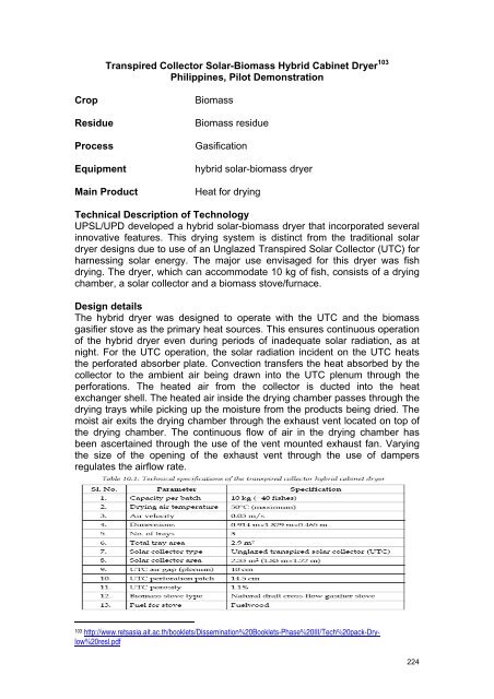
Solar-Biomass Hybrid Cabinet Dryer
- Page 108 and 109:
Two doors were designed for easy lo
- Page 110 and 111:
Asbestos gaskets are used while con
- Page 112 and 113:
The ash scraper slides through a cy
- Page 114 and 115:
flange attached at its bottom; this
- Page 116 and 117:
Other fuels such as saw dust brique
- Page 118 and 119:
The completed hybrid solar-biomass
- Page 120 and 121:
Greenfire 41 USA, Commercial Crop R
- Page 122 and 123:
Mayon Turbo Stove and Lo Trau Stove
- Page 124 and 125:
Social Considerations The stove was
- Page 126 and 127:
Commercial Gasifier 49 Philippines,
- Page 128 and 129:
The Modul-Pak ® boiler is a hybrid
- Page 130 and 131:
Suppliers Energy Quest, Inc. 850 So
- Page 132 and 133:
as well as the extraction, recovery
- Page 134 and 135:
oil production period in the mills.
- Page 136 and 137:
weatherproof and sound-attenuating
- Page 138 and 139:
Primenergy R-18 Gasifier producing
- Page 140 and 141:
Low-cost 500 kW thermal rice hull c
- Page 142 and 143:
Kansai Carbonized Rice Husk Gasifie
- Page 144 and 145:
Colusa Rice Straw / Hulls Technolog
- Page 146 and 147:
The customized harvester collects t
- Page 148 and 149:
Rice Husk Gasifier Philippines, Com
- Page 150 and 151:
2.5 MW Cogeneration Plant 65 Thaila
- Page 152 and 153:
San San Rice Husk Stove Myanmar, Co
- Page 154 and 155:
The technology of rice husk gasifie
- Page 156 and 157:
of trees can be controlled. This wo
- Page 158 and 159:
includes an automatic feeder, which
- Page 160 and 161:
Maligaya Rice Hull Stove 74 Philipp
- Page 162 and 163:
Parameters for Procurement Specific
- Page 164 and 165:
162
- Page 166 and 167:
a 100KW capacity Rice-Husk based Ga
- Page 168 and 169:
Rice husk briquette fuel 84 Banglad
- Page 170 and 171:
aised to US$ 6.84 million from the
- Page 172 and 173:
ease of removal of the char, a grat
- Page 174 and 175:
The rice husk gas burner for bakery
- Page 176 and 177: Engineering and Environmental Manag
- Page 178 and 179: Depending on the type of fuel it ha
- Page 180 and 181: mode, all of the steam directed to
- Page 182 and 183: pyrolysis) with air or oxygen at te
- Page 184 and 185: R S for in-kind repair of boilers a
- Page 186 and 187: Wood Biomass Electricity Generator
- Page 188 and 189: Advantages to Developing Countries
- Page 190 and 191: Celunol's "wet" biomass conversion
- Page 192 and 193: up to 1.3 million liters of cellulo
- Page 194 and 195: This process is done in shredder ma
- Page 196 and 197: The minimal price established is $C
- Page 198 and 199: 196
- Page 200 and 201: Telephone (303) 933-3135 FAX (303)
- Page 202 and 203: Solar-Biomass Hybrid Cabinet Dryer
- Page 204 and 205: The stove uses cylindrical honeycom
- Page 206 and 207: Research Centre for Applied Science
- Page 208 and 209: air. Woody biomass available in ple
- Page 210 and 211: Dry Grind Ethanol 99 USA, Under Con
- Page 212 and 213: Price Ethanol sells as a commodity
- Page 214 and 215: 1 Figure 1. Design of the dryer Det
- Page 216 and 217: footings made of brick and mortar.
- Page 218 and 219: placed inside mild steel shell of l
- Page 220 and 221: Biological Hydrogen Production from
- Page 222 and 223: ioprocess for hydrogen production f
- Page 224 and 225: a. Reactor: This was a downdraft, t
- Page 228 and 229: Drying chamber The drying chamber c
- Page 230 and 231: Annexure 3 EST for Energy Conversio
- Page 232 and 233: Detailed Process Description Figure
- Page 234 and 235: Forest Products Research and Develo
- Page 236 and 237: Advanced Gasification-Combustion (A
- Page 238 and 239: Wood wool cement board (WWCB) Cemen
- Page 240 and 241: Furnace-Type Lumber Dryer 105 Phili
- Page 242 and 243: (i) Charring Drum. The charring dru
- Page 244 and 245: The mould set is filled with the mi
- Page 246 and 247: Solar Collector The solar collector
- Page 248 and 249: Fluidized Bed Combustor for Steam G
- Page 250 and 251: Small-Scale Biomass Pyrolyzer for F
- Page 252 and 253: chips) aside from palay and allows
- Page 254 and 255: Detailed Process Description There
- Page 256 and 257: The IRRI DR-1 Batch Dryer 117 Phili
- Page 258 and 259: Rice Hull Furnace attached to a blo
- Page 260 and 261: was not continuously discharged fro
- Page 262 and 263: Detailed Process Description Drying
- Page 264 and 265: Rice Hull Ash Cement (RHAC) Hollow
- Page 266 and 267: Annexure 4 EST for Material Convers
- Page 268 and 269: Through a joint venture component m
- Page 270 and 271: Abaca Mechanical Tuxer 129 Philippi
- Page 272 and 273: Economic instruments for overcoming
- Page 274 and 275: Figure 2. Fiber Twisting Machine
- Page 276 and 277:
Example of Real Life Applications C
- Page 278 and 279:
Main Products: Cellulosic Ethanol O
- Page 280 and 281:
converted to a high-carbon char mat
- Page 282 and 283:
NovaGreen Biomass Ethanol Separatio
- Page 284 and 285:
Advantages to Developing Countries
- Page 286 and 287:
Detailed Process Description 133 On
- Page 288 and 289:
286
- Page 290 and 291:
agricultural waste could theoretica
- Page 292 and 293:
downstream value-added products whe
- Page 294 and 295:
Bio-Enriched Method (Trichoderma an
- Page 296 and 297:
Increases yield. Improves water-hol
- Page 298 and 299:
Environmental Considerations 141 Co
- Page 300 and 301:
298
- Page 302 and 303:
150 150 http://www.kinseiseishi.co.
- Page 304 and 305:
152 Type of non-woven materials Che
- Page 306 and 307:
Bale as feedstock USA, Commercial C
- Page 308 and 309:
Price of Machine : refer to the tab
- Page 310 and 311:
2. Cooking the Fiber: A rope is lai
- Page 312 and 313:
9. Weaving: Water is sprayed on the
- Page 314 and 315:
Decorticating Machine and Motorised
- Page 316 and 317:
usually contains two spindles set i
- Page 318 and 319:
tradition and, moreover, the range
- Page 320 and 321:
318
- Page 322 and 323:
Over 3.5 million coconut farmers ar
- Page 324 and 325:
The blades also propel coir fibre t
- Page 326 and 327:
Economic instruments for overcoming
- Page 328 and 329:
first using the drum method or the
- Page 330 and 331:
Job Potential: Farmers' cooperative
- Page 332 and 333:
Soundproofing and Insulating Materi
- Page 334 and 335:
The environmental impact is signifi
- Page 336 and 337:
. Suppliers K.E.F.I. - Kenaf Eco Fi
- Page 338 and 339:
Detailed Process Descriptions: 1. H
- Page 340 and 341:
Examples of Real Life Applications
- Page 342 and 343:
In a two-stage setup, the target wi
- Page 344 and 345:
companies with expertise in this we
- Page 346 and 347:
Mezcal Production from Maguey Phili
- Page 348 and 349:
5. Crushing the agave. The roasted
- Page 350 and 351:
Method of Propagation Applying fert
- Page 352 and 353:
Main Products 198 Abaca fiber comes
- Page 354 and 355:
Being a high-priced fabric has prac
- Page 356 and 357:
Detailed Process Description 202 Me
- Page 358 and 359:
Rice Husk basket Burner India, Comm
- Page 360 and 361:
The ash should be white or grey wit
- Page 362 and 363:
Paper from Rice Straw Cyprus, Comme
- Page 364 and 365:
1. Vatting - Fill your vat halfway
- Page 366 and 367:
Ethanol Production by Acid Hydrolys
- Page 368 and 369:
improvements would provide cost sav
- Page 370 and 371:
Detailed Process Description 7. Ric
- Page 372 and 373:
Plywood from Sorghum China, Commerc
- Page 374 and 375:
Example of Real Life Applications L
- Page 376 and 377:
Figure 1. Schematic of gasifier-pow
- Page 378 and 379:
hull is a processing by-product of
- Page 380 and 381:
The size of the mill or number of m
- Page 382 and 383:
Figure 3. A 12-ft continuous evapor
- Page 384 and 385:
The finished syrup is thoroughly st
- Page 386 and 387:
Drinking Vinegar from Sweet Sorghum
- Page 388 and 389:
only four months. Ethanol, a cheape
- Page 390 and 391:
Davis & Standard Twin Screw Extrude
- Page 392 and 393:
Environmental and Social Considerat
- Page 394 and 395:
Annexure 5 EST for Material Convers
- Page 396 and 397:
Detailed Process Description Figure
- Page 398 and 399:
operational analysis be carried out
- Page 400 and 401:
Figure 2. Hopper or Feeder The comp
- Page 402 and 403:
Broin Fractionation (BFRAC) 218 USA
- Page 404 and 405:
Collaboration with other companies
- Page 406 and 407:
NET INCOME Before Tax = 237, 600 -
- Page 408 and 409:
Cornstalk Flash Volatilization USA,
- Page 410 and 411:
Decentralized Wastewater Treatment
- Page 412 and 413:
degrades the wastes. The algal pond
- Page 414 and 415:
Job Potential: 231 Preparing the so
- Page 416 and 417:
Annexure 6 EST for Material Convers
- Page 418 and 419:
Operations and Maintenance Requirem
- Page 420 and 421:
Detailed Process Description There
- Page 422 and 423:
Biochar 237 USA, Research Crop Resi
- Page 424 and 425:
422
- Page 426 and 427:
424
- Page 428 and 429:
Detailed Process Description: 241 2
- Page 430 and 431:
In addition to functioning as a thi
- Page 432 and 433:
The underflow from the first stage
- Page 434 and 435:
y essentially dry process technique
- Page 436 and 437:
industrial uses. It consists of mol
- Page 438 and 439:
yeast for high alcohol, and high-te
- Page 440 and 441:
About the UNEP Division of Technolo