The significance of coherent flow structures for the turbulent mixing ...
The significance of coherent flow structures for the turbulent mixing ...
The significance of coherent flow structures for the turbulent mixing ...

Create successful ePaper yourself
Turn your PDF publications into a flip-book with our unique Google optimized e-Paper software.
7 Investigation <strong>of</strong> <strong>the</strong> yz-plane<br />
light-sheet by turning <strong>the</strong> cylindrical lens in <strong>the</strong> light-sheet optic. <strong>The</strong> observation angle <strong>for</strong><br />
each camera in angular imaging configuration with Scheimpflug correction is shown in <strong>the</strong><br />
following table along with <strong>the</strong> exact positions <strong>of</strong> <strong>the</strong> master cameras (1 and 2 in figure 7.1)<br />
with respect to <strong>the</strong> centre <strong>of</strong> <strong>the</strong> field <strong>of</strong> view (all asymmetries have been taken into account<br />
<strong>for</strong> <strong>the</strong> calculation <strong>of</strong> <strong>the</strong> three velocity components). Four 180 mm lenses (Carl Zeiss)<br />
camera Î [mm] Ï [mm] f@g [mm]<br />
¯<br />
[deg]<br />
1 -1570 1464 2143 42.9<br />
2 -1560 -1463 2140 43.2<br />
TABLE 7.1: Position and observation distance <strong>of</strong> <strong>the</strong> master cameras with respect to <strong>the</strong> centre <strong>of</strong> each<br />
field <strong>of</strong> view (meeting point <strong>of</strong> optical axis) and corresponding observation angles.<br />
a<br />
b<br />
40 mm separation<br />
~86°<br />
main <strong>flow</strong>-direction<br />
6<br />
5<br />
4<br />
7<br />
8<br />
test-section 3<br />
x<br />
2<br />
side window<br />
z<br />
1<br />
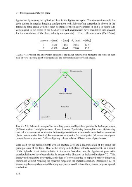
FIGURE 7.1: Schematic set-up <strong>of</strong> <strong>the</strong> recording system and light-sheet position <strong>for</strong> both experiments<br />
(different scales). 1-4 digital cameras, 5 lens, 6 mirror, 7 polarising beam-splitter cube, 8 absorbing<br />
material, a measurement location <strong>for</strong> 1st investigation (40 mm separation between both measurement<br />
planes in stream-wise direction), b measurement location <strong>for</strong> 2nd investigation (all measurement positions<br />
at <strong>the</strong> same location). Different light ray colours indicate different states <strong>of</strong> polarisation.<br />
were used <strong>for</strong> <strong>the</strong> measurements with an aperture <strong>of</strong> 8 and a magnification <strong>of</strong> 1/6 along <strong>the</strong><br />
principal axis <strong>of</strong> <strong>the</strong> lens. Due to <strong>the</strong> strong out-<strong>of</strong>-plane velocity component, as a result<br />
<strong>of</strong> <strong>the</strong> light-sheet orientation relative to <strong>the</strong> main <strong>flow</strong> direction, <strong>the</strong> light-sheet pairs with<br />
equal polarisation have been shifted in stream-wise direction as indicated in figure 7.2. This<br />
improves <strong>the</strong> signal to noise ratio, as <strong>the</strong> loss-<strong>of</strong>-correlation due to unpaired particle images is<br />
minimised without reducing <strong>the</strong> dynamic range and <strong>the</strong> spatial resolution. Decreasing Í_] or<br />
increasing <strong>the</strong> magnification <strong>of</strong> <strong>the</strong> imaging system would reduce <strong>the</strong> dynamic range or spatial<br />
resolution.<br />
136