The significance of coherent flow structures for the turbulent mixing ...
The significance of coherent flow structures for the turbulent mixing ...
The significance of coherent flow structures for the turbulent mixing ...

You also want an ePaper? Increase the reach of your titles
YUMPU automatically turns print PDFs into web optimized ePapers that Google loves.
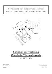
6.1 Experimental set-up<br />
<strong>the</strong> (virtual) slave cameras 1 and 2, located behind <strong>the</strong> mirrors, are not presented in <strong>the</strong> table<br />
as <strong>the</strong>se can be considered as identical with <strong>the</strong> corresponding master cameras 3 and 4.<br />
y<br />
x<br />
main <strong>flow</strong>-direction<br />
c<br />
a<br />
10 wall-units light-sheet separation<br />
~94°<br />
b<br />
8<br />
7<br />
6<br />
5<br />
4<br />
2<br />
1<br />
3<br />
FIGURE 6.2: Experimental set-up <strong>for</strong> ÚQ -investigation. 1-4 digital cameras, 5 lens, 6 mirror, 7 polarising<br />
beam-splitter cube, 8 absorbing material.<br />
camera á [mm] Ä [mm] OP [mm] R [deg]<br />
3 628 -573 850 47.1<br />
4 -608 -565 829 47.6<br />
TABLE 6.1: Camera position, observation<br />
distances and viewing angles with respect<br />
to <strong>the</strong> centre <strong>of</strong> <strong>the</strong> field <strong>of</strong> view.<br />
For magnification and field <strong>of</strong> view adjustments each Scheimpflug-adapter was mounted<br />
on a two-axis micrometer translation stage, and <strong>the</strong> polarising beam splitter-cubes and mirrors<br />
in front <strong>of</strong> <strong>the</strong> lenses were connected to two-axis tilt-rotation stages and gimbal mirror mounts.<br />
To obtain ideal particle images <strong>for</strong> <strong>the</strong> image analysis algorithms ÓöÎ<br />
(bright circles, pixel in<br />
diameter, surrounded by a dark background), <strong>the</strong> imaging <strong>of</strong> <strong>the</strong> field <strong>of</strong> view was per<strong>for</strong>med<br />
by means <strong>of</strong> 100 mm Carl Zeiss lenses with an aperture <strong>of</strong> 8. This leads to a complete erasure<br />
<strong>of</strong> all optical aberrations and out-<strong>of</strong>-focus effects. <strong>The</strong> arrangement was installed<br />
<br />
below<br />
<strong>the</strong> wind-tunnel, as shown in figure 6.2. <strong>The</strong> mean observation S<br />
distance was mm and<br />
*:U<br />
<strong>the</strong><br />
opening angle between <strong>the</strong> left and right camera systems was T set to to resolve <strong>the</strong> out-<strong>of</strong>plane<br />
motion with sufficient accuracy according to figure 3.5. This is important because <strong>the</strong><br />
out-<strong>of</strong>-plane component is required to calculate <strong>the</strong> dominant Reynolds shear-stress component<br />
V turb W<br />
glued on an aluminium plate and attached with a micrometer translation stage in such a way<br />
that a parallel motion <strong>of</strong> <strong>the</strong> grid could be achieved in vertical direction. This grid was aligned<br />
with each light-sheet one after ano<strong>the</strong>r and recorded each time with <strong>the</strong> four cameras (be<strong>for</strong>e<br />
and after <strong>the</strong> experiment in order to pro<strong>of</strong> <strong>the</strong> conservation <strong>of</strong> <strong>the</strong> boundary conditions during<br />
<strong>the</strong> experiment). As any horizontal translation <strong>of</strong> <strong>the</strong> target could be excluded with this device,<br />
Î& 6(7 . For <strong>the</strong> calibration <strong>of</strong> <strong>the</strong> system a regular grid with Ó mm line spacing was<br />
99