The significance of coherent flow structures for the turbulent mixing ...
The significance of coherent flow structures for the turbulent mixing ...
The significance of coherent flow structures for the turbulent mixing ...

You also want an ePaper? Increase the reach of your titles
YUMPU automatically turns print PDFs into web optimized ePapers that Google loves.
5.2 Experimental set-up<br />
α4 α3<br />
α2<br />
α1<br />
main <strong>flow</strong>-direction<br />
4<br />
test-section<br />
3<br />
x<br />
2<br />
side window<br />
z<br />
1<br />
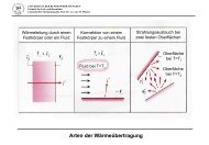
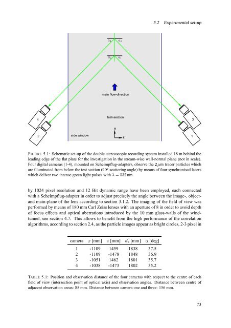
FIGURE 5.1: Schematic set-up <strong>of</strong> <strong>the</strong> double stereoscopic recording system installed 18 m behind <strong>the</strong><br />
leading edge <strong>of</strong> <strong>the</strong> flat plate <strong>for</strong> <strong>the</strong> investigation in <strong>the</strong> stream-wise wall-normal plane (not in scale).<br />
Four digital cameras (1-4), mounted on Scheimpflug-adapters, observe opQq <strong>the</strong> tracer particles which<br />
are illuminated from below <strong>the</strong> test section (rs À scattering angle) by means <strong>of</strong> four synchronised lasers<br />
which deliver two intense green light pulses with t#uBv¥w¥o nm.<br />
by 1024 pixel resolution and 12 Bit dynamic range have been employed, each connected<br />
with a Scheimpflug-adapter in order to adjust precisely <strong>the</strong> angle between <strong>the</strong> image-, objectand<br />
main-plane <strong>of</strong> <strong>the</strong> lens according to section 3.1.2. <strong>The</strong> imaging <strong>of</strong> <strong>the</strong> field <strong>of</strong> view was<br />
per<strong>for</strong>med by means <strong>of</strong> 180 mm Carl Zeiss lenses with an aperture <strong>of</strong> 8 in order to avoid depth<br />
<strong>of</strong> focus effects and optical aberrations introduced by <strong>the</strong> 10 mm glass-walls <strong>of</strong> <strong>the</strong> windtunnel,<br />
see section 4.7. This allows to benefit from <strong>the</strong> high per<strong>for</strong>mance <strong>of</strong> <strong>the</strong> correlation<br />
algorithms, according to section 2.4, as <strong>the</strong> particle images appear as bright circles, 2-3 pixel in<br />
camera 9 [mm] x [mm]<br />
â<br />
?nm<br />
[mm] [deg]<br />
1 -1109 1459 1838 37.5<br />
2 -1109 -1478 1848 36.9<br />
3 -1051 1462 1801 35.7<br />
4 -1038 -1473 1802 35.2<br />
TABLE 5.1: Position and observation distance <strong>of</strong> <strong>the</strong> four cameras with respect to <strong>the</strong> centre <strong>of</strong> each<br />
field <strong>of</strong> view (intersection point <strong>of</strong> optical axis) and observation angles. Distance between centre <strong>of</strong><br />
adjacent observation areas: 85 mm. Distance between camera one and three: 156 mm.<br />
73