The significance of coherent flow structures for the turbulent mixing ...
The significance of coherent flow structures for the turbulent mixing ...
The significance of coherent flow structures for the turbulent mixing ...

You also want an ePaper? Increase the reach of your titles
YUMPU automatically turns print PDFs into web optimized ePapers that Google loves.
º¹<br />
n<br />
4.7 Monochromatic aberrations<br />
α 1<br />
Z<br />
n<br />
n<br />
1<br />
2<br />
z<br />
α 2<br />
X<br />
θ<br />
1<br />
θ 2<br />
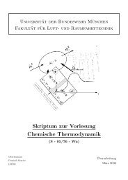
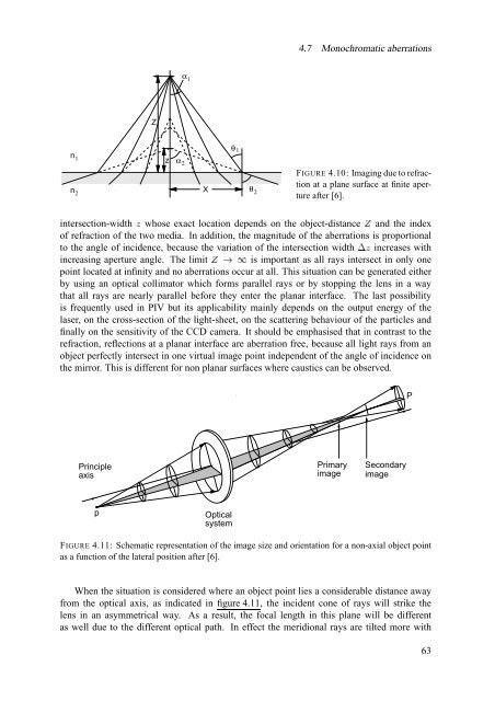
FIGURE 4.10: Imaging due to refraction<br />
at a plane surface at finite aperture<br />
after [6].<br />
intersection-width n whose exact location depends on <strong>the</strong> object-distance ¨<br />
and <strong>the</strong> index<br />
<strong>of</strong> refraction <strong>of</strong> <strong>the</strong> two media. In addition, <strong>the</strong> magnitude <strong>of</strong> <strong>the</strong> aberrations is proportional<br />
to <strong>the</strong> angle <strong>of</strong> incidence, because <strong>the</strong> variation <strong>of</strong> <strong>the</strong> intersection ³ width increases with<br />
increasing aperture angle. <strong>The</strong> limit ¨µ´ is important as all rays intersect in only one<br />
point located at infinity and no aberrations occur at all. This situation can be generated ei<strong>the</strong>r<br />
by using an optical collimator which <strong>for</strong>ms parallel rays or by stopping <strong>the</strong> lens in a way<br />
that all rays are nearly parallel be<strong>for</strong>e <strong>the</strong>y enter <strong>the</strong> planar interface. <strong>The</strong> last possibility<br />
is frequently used in PIV but its applicability mainly depends on <strong>the</strong> output energy <strong>of</strong> <strong>the</strong><br />
laser, on <strong>the</strong> cross-section <strong>of</strong> <strong>the</strong> light-sheet, on <strong>the</strong> scattering behaviour <strong>of</strong> <strong>the</strong> particles and<br />
finally on <strong>the</strong> sensitivity <strong>of</strong> <strong>the</strong> CCD camera. It should be emphasised that in contrast to <strong>the</strong><br />
refraction, reflections at a planar interface are aberration free, because all light rays from an<br />
object perfectly intersect in one virtual image point independent <strong>of</strong> <strong>the</strong> angle <strong>of</strong> incidence on<br />
<strong>the</strong> mirror. This is different <strong>for</strong> non planar surfaces where caustics can be observed.<br />
P<br />
¸¸¸¸¸¸¸¸¸¸¸¸¸¸¸¸¸¸¸¸¸¸¸¸¸¸¸¸¸¸¸¸¸¸¸¸¸¸¸¸¸<br />
·········································<br />
Principle<br />
axis<br />
Primary<br />
image<br />
Secondary<br />
image<br />
·········································<br />
¸¸¸¸¸¸¸¸¸¸¸¸¸¸¸¸¸¸¸¸¸¸¸¸¸¸¸¸¸¸¸¸¸¸¸¸¸¸¸¸¸<br />
·········································<br />
»»»»»»»»»»»»»»»»»»»»»»»»»»»<br />
¼¼¼¼¼¼¼¼¼¼¼¼¼¼¼¼¼¼¼¼¼¼¼¼¼¼¼<br />
»»»»»»»»»»»»»»»»»»»»»»»»»»»<br />
·········································<br />
¸¸¸¸¸¸¸¸¸¸¸¸¸¸¸¸¸¸¸¸¸¸¸¸¸¸¸¸¸¸¸¸¸¸¸¸¸¸¸¸¸<br />
·········································<br />
¸¸¸¸¸¸¸¸¸¸¸¸¸¸¸¸¸¸¸¸¸¸¸¸¸¸¸¸¸¸¸¸¸¸¸¸¸¸¸¸¸<br />
·········································<br />
¸¸¸¸¸¸¸¸¸¸¸¸¸¸¸¸¸¸¸¸¸¸¸¸¸¸¸¸¸¸¸¸¸¸¸¸¸¸¸¸¸<br />
·········································<br />
¸¸¸¸¸¸¸¸¸¸¸¸¸¸¸¸¸¸¸¸¸¸¸¸¸¸¸¸¸¸¸¸¸¸¸¸¸¸¸¸¸<br />
·········································<br />
¸¸¸¸¸¸¸¸¸¸¸¸¸¸¸¸¸¸¸¸¸¸¸¸¸¸¸¸¸¸¸¸¸¸¸¸¸¸¸¸¸<br />
·········································<br />
¸¸¸¸¸¸¸¸¸¸¸¸¸¸¸¸¸¸¸¸¸¸¸¸¸¸¸¸¸¸¸¸¸¸¸¸¸¸¸¸¸<br />
·········································<br />
¸¸¸¸¸¸¸¸¸¸¸¸¸¸¸¸¸¸¸¸¸¸¸¸¸¸¸¸¸¸¸¸¸¸¸¸¸¸¸¸¸<br />
·········································<br />
¸¸¸¸¸¸¸¸¸¸¸¸¸¸¸¸¸¸¸¸¸¸¸¸¸¸¸¸¸¸¸¸¸¸¸¸¸¸¸¸¸<br />
·········································<br />
¸¸¸¸¸¸¸¸¸¸¸¸¸¸¸¸¸¸¸¸¸¸¸¸¸¸¸¸¸¸¸¸¸¸¸¸¸¸¸¸¸<br />
·········································<br />
¸¸¸¸¸¸¸¸¸¸¸¸¸¸¸¸¸¸¸¸¸¸¸¸¸¸¸¸¸¸¸¸¸¸¸¸¸¸¸¸¸<br />
·········································<br />
¸¸¸¸¸¸¸¸¸¸¸¸¸¸¸¸¸¸¸¸¸¸¸¸¸¸¸¸¸¸¸¸¸¸¸¸¸¸¸¸¸<br />
·········································<br />
¸¸¸¸¸¸¸¸¸¸¸¸¸¸¸¸¸¸¸¸¸¸¸¸¸¸¸¸¸¸¸¸¸¸¸¸¸¸¸¸¸<br />
·········································<br />
¸¸¸¸¸¸¸¸¸¸¸¸¸¸¸¸¸¸¸¸¸¸¸¸¸¸¸¸¸¸¸¸¸¸¸¸¸¸¸¸¸<br />
·········································<br />
p<br />
Optical<br />
system<br />
»»»»»»»»»»»»»»»»»»»»»»»»»»»<br />
¼¼¼¼¼¼¼¼¼¼¼¼¼¼¼¼¼¼¼¼¼¼¼¼¼¼¼<br />
¼¼¼¼¼¼¼¼¼¼¼¼¼¼¼¼¼¼¼¼¼¼¼¼¼¼¼<br />
»»»»»»»»»»»»»»»»»»»»»»»»»»»<br />
¼¼¼¼¼¼¼¼¼¼¼¼¼¼¼¼¼¼¼¼¼¼¼¼¼¼¼<br />
»»»»»»»»»»»»»»»»»»»»»»»»»»»<br />
¼¼¼¼¼¼¼¼¼¼¼¼¼¼¼¼¼¼¼¼¼¼¼¼¼¼¼<br />
»»»»»»»»»»»»»»»»»»»»»»»»»»»<br />
¼¼¼¼¼¼¼¼¼¼¼¼¼¼¼¼¼¼¼¼¼¼¼¼¼¼¼<br />
»»»»»»»»»»»»»»»»»»»»»»»»»»»<br />
¼¼¼¼¼¼¼¼¼¼¼¼¼¼¼¼¼¼¼¼¼¼¼¼¼¼¼<br />
»»»»»»»»»»»»»»»»»»»»»»»»»»»<br />
¼¼¼¼¼¼¼¼¼¼¼¼¼¼¼¼¼¼¼¼¼¼¼¼¼¼¼<br />
»»»»»»»»»»»»»»»»»»»»»»»»»»»<br />
¼¼¼¼¼¼¼¼¼¼¼¼¼¼¼¼¼¼¼¼¼¼¼¼¼¼¼<br />
»»»»»»»»»»»»»»»»»»»»»»»»»»»<br />
¼¼¼¼¼¼¼¼¼¼¼¼¼¼¼¼¼¼¼¼¼¼¼¼¼¼¼<br />
»»»»»»»»»»»»»»»»»»»»»»»»»»»<br />
¼¼¼¼¼¼¼¼¼¼¼¼¼¼¼¼¼¼¼¼¼¼¼¼¼¼¼<br />
»»»»»»»»»»»»»»»»»»»»»»»»»»»<br />
¼¼¼¼¼¼¼¼¼¼¼¼¼¼¼¼¼¼¼¼¼¼¼¼¼¼¼<br />
»»»»»»»»»»»»»»»»»»»»»»»»»»»<br />
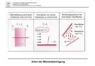
FIGURE 4.11: Schematic representation <strong>of</strong> <strong>the</strong> image size and orientation <strong>for</strong> a non-axial object point<br />
as a function <strong>of</strong> <strong>the</strong> lateral position after [6].<br />
When <strong>the</strong> situation is considered where an object point lies a considerable distance away<br />
from <strong>the</strong> optical axis, as indicated in figure 4.11, <strong>the</strong> incident cone <strong>of</strong> rays will strike <strong>the</strong><br />
lens in an asymmetrical way. As a result, <strong>the</strong> focal length in this plane will be different<br />
as well due to <strong>the</strong> different optical path. In effect <strong>the</strong> meridional rays are tilted more with<br />
63