Heads-Up Display Modes 35 - Metaboli
Heads-Up Display Modes 35 - Metaboli
Heads-Up Display Modes 35 - Metaboli

You also want an ePaper? Increase the reach of your titles
YUMPU automatically turns print PDFs into web optimized ePapers that Google loves.
12 Aircraft Cockpits<br />
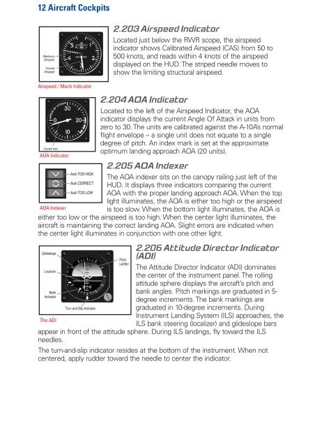
2.203 Airspeed Indicator<br />
Located just below the RWR scope, the airspeed<br />
indicator shows Calibrated Airspeed (CAS) from 50 to<br />
500 knots, and reads within 4 knots of the airspeed<br />
displayed on the HUD. The striped needle moves to<br />
show the limiting structural airspeed.<br />
Airspeed / Mach Indicator<br />
AOA Indicator<br />
2.204 AOA Indicator<br />
Located to the left of the Airspeed Indicator, the AOA<br />
indicator displays the current Angle Of Attack in units from<br />
zero to 30. The units are calibrated against the A-10A’s normal<br />
flight envelope – a single unit does not equate to a single<br />
degree of pitch. An index mark is set at the approximate<br />
optimum landing approach AOA (20 units).<br />
2.205 AOA Indexer<br />
The AOA indexer sits on the canopy railing just left of the<br />
HUD. It displays three indicators comparing the current<br />
AOA with the proper landing approach AOA. When the top<br />
light illuminates, the AOA is either too high or the airspeed<br />
AOA Indexer<br />
is too slow. When the bottom light illuminates, the AOA is<br />
either too low or the airspeed is too high. When the center light illuminates, the<br />
aircraft is maintaining the correct landing AOA. Slight errors are indicated when<br />
the center light illuminates in conjunction with one other light.<br />
2.206 Attitude Director Indicator<br />
(ADI)<br />
The Attitude Director Indicator (ADI) dominates<br />
the center of the instrument panel. The rolling<br />
attitude sphere displays the aircraft’s pitch and<br />
bank angles. Pitch markings are graduated in 5-<br />
degree increments. The bank markings are<br />
graduated in 10-degree increments. During<br />
Instrument Landing System (ILS) approaches, the<br />
The ADI<br />
ILS bank steering (localizer) and glideslope bars<br />
appear in front of the attitude sphere. During ILS landings, fly toward the ILS<br />
needles.<br />
The turn-and-slip indicator resides at the bottom of the instrument. When not<br />
centered, apply rudder toward the needle to center the indicator.