Heads-Up Display Modes 35 - Metaboli
Heads-Up Display Modes 35 - Metaboli
Heads-Up Display Modes 35 - Metaboli

You also want an ePaper? Increase the reach of your titles
YUMPU automatically turns print PDFs into web optimized ePapers that Google loves.
Sensors 71<br />
hLarger patterns take longer to scan. Fast-moving targets can move<br />
completely through the pattern undetected before a radar beam reaches<br />
that portion of the scan.<br />
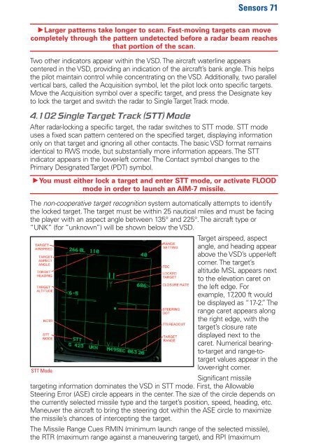
Two other indicators appear within the VSD. The aircraft waterline appears<br />
centered in the VSD, providing an indication of the aircraft’s bank angle. This helps<br />
the pilot maintain control while concentrating on the VSD. Additionally, two parallel<br />
vertical bars, called the Acquisition symbol, let the pilot lock onto specific targets.<br />
Move the Acquisition symbol over a specific target, and press the Designate key<br />
to lock the target and switch the radar to Single Target Track mode.<br />
4.102 Single Target Track (STT) Mode<br />
After radar-locking a specific target, the radar switches to STT mode. STT mode<br />
uses a fixed scan pattern centered on the specified target, displaying information<br />
only on that target and ignoring all other contacts. The basic VSD format remains<br />
identical to RWS mode, but substantially more information appears. The STT<br />
indicator appears in the lower-left corner. The Contact symbol changes to the<br />
Primary Designated Target (PDT) symbol.<br />
hYou must either lock a target and enter STT mode, or activate FLOOD<br />
mode in order to launch an AIM-7 missile.<br />
The non-cooperative target recognition system automatically attempts to identify<br />
the locked target. The target must be within 25 nautical miles and must be facing<br />
the player with an aspect angle between 1<strong>35</strong>° and 225°. The aircraft type or<br />
“UNK” (for “unknown”) will be shown below the VSD.<br />
Target airspeed, aspect<br />
angle, and heading appear<br />
above the VSD’s upper-left<br />
corner. The target’s<br />
altitude MSL appears next<br />
to the elevation caret on<br />
the left edge. For<br />
example, 17,200 ft would<br />
be displayed as “17-2.” The<br />
range caret appears along<br />
the right edge, with the<br />
target’s closure rate<br />
displayed next to the<br />
caret. Numerical bearingto-target<br />
and range-totarget<br />
values appear in the<br />
lower-right corner.<br />
STT Mode<br />
Significant missile<br />
targeting information dominates the VSD in STT mode. First, the Allowable<br />
Steering Error (ASE) circle appears in the center. The size of the circle depends on<br />
the currently selected missile type and the target’s position, speed, heading, etc.<br />
Maneuver the aircraft to bring the steering dot within the ASE circle to maximize<br />
the missile’s chances of intercepting the target.<br />
The Missile Range Cues RMIN (minimum launch range of the selected missile),<br />
the RTR (maximum range against a maneuvering target), and RPI (maximum