Heads-Up Display Modes 35 - Metaboli
Heads-Up Display Modes 35 - Metaboli
Heads-Up Display Modes 35 - Metaboli

You also want an ePaper? Increase the reach of your titles
YUMPU automatically turns print PDFs into web optimized ePapers that Google loves.
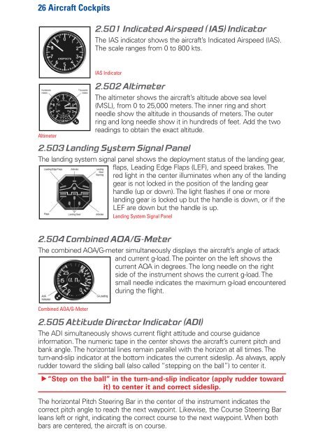
26 Aircraft Cockpits<br />
2.501 Indicated Airspeed ( IAS) Indicator<br />
The IAS indicator shows the aircraft’s Indicated Airspeed (IAS).<br />
The scale ranges from 0 to 800 kts.<br />
IAS Indicator<br />
Altimeter<br />
2.502 Altimeter<br />
The altimeter shows the aircraft’s altitude above sea level<br />
(MSL), from 0 to 25,000 meters. The inner ring and short<br />
needle show the altitude in thousands of meters. The outer<br />
ring and long needle show it in hundreds of feet. Add the two<br />
readings to obtain the exact altitude.<br />
2.503 Landing System Signal Panel<br />
The landing system signal panel shows the deployment status of the landing gear,<br />
flaps, Leading Edge Flaps (LEF), and speed brakes. The<br />
red light in the center illuminates when any of the landing<br />
gear is not locked in the position of the landing gear<br />
handle (up or down). The light flashes if one or more<br />
landing gear is locked up but the handle is down, or if the<br />
LEF are down but the handle is up.<br />
Landing System Signal Panel<br />
2.504 Combined AOA/G-Meter<br />
The combined AOA/G-meter simultaneously displays the aircraft’s angle of attack<br />
and current g-load. The pointer on the left shows the<br />
current AOA in degrees. The long needle on the right<br />
side of the instrument shows the current g-load. The<br />
small needle indicates the maximum g-load encountered<br />
during the flight.<br />
Combined AOA/G-Meter<br />
2.505 Attitude Director Indicator (ADI)<br />
The ADI simultaneously shows current flight attitude and course guidance<br />
information. The numeric tape in the center shows the aircraft’s current pitch and<br />
bank angle. The horizontal lines remain parallel with the horizon at all times. The<br />
turn-and-slip indicator at the bottom indicates the current sideslip. As always, apply<br />
rudder toward the sliding ball (also called “stepping on the ball”) to center it.<br />
h“Step on the ball” in the turn-and-slip indicator (apply rudder toward<br />
it) to center it and correct sideslip.<br />
The horizontal Pitch Steering Bar in the center of the instrument indicates the<br />
correct pitch angle to reach the next waypoint. Likewise, the Course Steering Bar<br />
leans left or right, indicating the correct course to the next waypoint. When both<br />
bars are centered, the aircraft is on course.