4 cylinders + 6 cylinders 4 cylinders + 6 cylinders - Steyr Motors
4 cylinders + 6 cylinders 4 cylinders + 6 cylinders - Steyr Motors
4 cylinders + 6 cylinders 4 cylinders + 6 cylinders - Steyr Motors
Create successful ePaper yourself
Turn your PDF publications into a flip-book with our unique Google optimized e-Paper software.
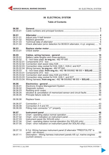
ToC SERVICE MANUAL MARINE ENGINES<br />
06 ELECTRICAL SYSTEM<br />
06 ELECTRICAL SYSTEM<br />
Table of Contents<br />
06.00 General......................................................................................................... 3<br />
06.00.01 Cable numbers and principal functions .......................................................... 3<br />
06.01 Alternator ..................................................................................................... 4<br />
06.01.01 Adjust poly-V-belt tension ............................................................................. 4<br />
06.01.02 Replace generator......................................................................................... 5<br />
06.01.03 Technical data of alternator .......................................................................... 6<br />
06.01.04 Check alternator (error detection for BOSCH alternator, 4 cyl. engines) .... 14<br />
06.03 Replace starter motor ............................................................................... 16<br />
06.03.01 Check starter ................................................................................................ 17<br />
06.05 Cables, wiring harness - general ............................................................. 19<br />
06.05.01 Battery cable lengths and cross-sections.................................................... 19<br />
06.05.02 E - box base plate; to eng.no.: 482 17 000 ................................................. 20<br />
06.05.02.01 Components of E - box ................................................................................ 21<br />
06.05.02.02 Connection start assist relay K28................................................................. 21<br />
06.05.02.03 Connection relay socket for K24, K26-1, K26-2, and K27............................ 21<br />
06.05.02.04 Wiring harness; to eng.no.: 482 17 000 ...................................................... 22<br />
06.05.03 E - box base plate; from eng.no.: 482 18 000/682 18 000 + SOLAS ......... 28<br />
06.05.03.01 Components of E - box ................................................................................ 29<br />
06.05.03.02 Connection start assist relay K28 and K26-2 ............................................... 29<br />
06.05.03.03 Connection relay socket for K24, K26-1, and K27 ....................................... 29<br />
06.05.03.04 Wiring harness; from eng.no.: 482 18 000/682 18 000 + SOLAS .............. 30<br />
06.06 Electronics - general .................................................................................. 36<br />
06.06.01 Electronic Engine Management System ..................................................... 36<br />
06.06.02 Diagnostic system ....................................................................................... 37<br />
06.06.03 Reading error codes.................................................................................... 38<br />
06.06.04 Idication & cancellation of memorized sensor and circuit faults .................. 39<br />
06.06.05 Principle failure code list ............................................................................. 40<br />
06.06.06 Replace fuses ............................................................................................. 42<br />
06.06.07 Connection J 1 ............................................................................................. 43<br />
06.06.08 Connection A 5 and X5 ................................................................................ 44<br />
06.06.09 Fitting main connector "J1" properly ............................................................ 45<br />
06.07 Instrument panel ....................................................................................... 46<br />
06.07.01 Chart - operating status normal operation................................................... 47<br />
06.07.02 Chart - error indication on instrument panel ................................................ 48<br />
06.07.03 Instrument panel (for SOLAS only) ............................................................. 52<br />
06.07.04 Chart - operating status normal operation (for SOLAS only) ...................... 53<br />
06.07.05 Chart - error indication on instrument panel (for SOLAS only) .................... 54<br />
06.07.10 6 Cyl. Wiring harness instrument panel (if alternator "PRESTOLITE" is<br />
used - old version)........................................................................................ 58<br />
06.07.11 Description - Wiring harness instrument panels 4/6 cyl. marine engines<br />
(current version) ........................................................................................... 62<br />
Z001019/0_6_July 2008 Page ELECTRICAL SYSTEM - 1


