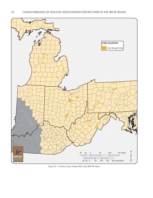
32 CHARACTERIZATION OF GEOLOGIC SEQUESTRATION OPPORTUNITIES IN THE <strong>MRCSP</strong> REGION EXPLANATION Gas Storage Fields P R O J E C T L I M I T 50 25 0 50 100 150 Miles 50 25 0 50 100 150 200 Kilometers ³ Figure 20.—Location of gas storage fields in the <strong>MRCSP</strong> region.
CO 2-SEQUESTRATION STORAGE CAPACITY FOR THE <strong>MRCSP</strong> PROJECT 33 CO 2 -SEQUESTRATION STORAGE CAPACITY FOR THE <strong>MRCSP</strong> PROJECT CO 2-STORAGE MECHANISMS IN GEOLOGIC FORMATIONS Carbon dioxide sequestration in geologic strata relies upon a number of different storage mechanisms that are based on sitespecific geologic conditions. Based on the geologic sequestration research conducted over the last decade by a number of researchers, these mechanisms are now fairly well described in published papers and proceedings of conferences such as the Greenhouse Gas Control Technology (GHGT) series organized by the International Energy Agency Greenhouse Gas R&D Programme (see www.ieagreen.org.uk for conference proceedings information) or in the Special <strong>Report</strong> on Carbon Dioxide Capture and Storage prepared by the Intergovernmental Panel on Climate Change (IPCC) (e.g. Houghton and others, 1996; 2001). The commonly discussed storage mechanisms are volumetric storage, solubility storage, adsorption storage, and mineral storage. Volumetric storage refers to the amount of CO 2 that is retained in the pore space of a geologic unit, generally as a supercritical phase retained by structural or stratigraphic traps or by the overlying cap-rock layers. Solubility storage involves dissolution of a part or all of the CO 2 into the formation waters of the geologic unit. Adsorption storage involves the holding of CO 2 molecules onto the fracture faces and into the matrix of organic-rich rock units, such as coal or black shale. Mineral storage involves the chemical reaction of CO 2 with the minerals and brine in the geologic unit. Under appropriate conditions, some chemical reactions may form a solid precipitate, permanently binding the carbon to the geologic unit. Mineral storage is not investigated as part of this report because the complex nature of the reactions and the uncertainty in reaction rates makes it difficult to determine the storage volumes on a regional scale. In addition to the types of formations and storage mechanisms evaluated in this report, basalt layers and salt caverns are also potential repositories for CO 2-storage; however, due to the early state of research for these options, they were not evaluated at this time for <strong>MRCSP</strong> region. CO 2 PROPERTIES Before the description of the calculation methods used for CO 2- storage capacity determinations can begin, it is important to briefly review the physical properties of CO 2, since these physical properties affect how much CO 2 can be placed into storage. The phase behavior of CO 2 is well understood and can be found in general chemical references such as Lemmon and others (2003) or in literature on enhanced oil recovery (e.g., Jarrell and others, 2002). Carbon dioxide can exist as four different phases (Figure 21), as a solid, liquid, gas, or as a super-critical gas. The triple point for solid, liquid, and gas is at -69.826º F (-56.57º C) and 75.2020672 psia (0.5185 MPa). At temperatures greater than 87.8º F (31.1º C) and pressures greater than 1,071 psia (7.38 MPa), CO 2 is in a super-critical state, behaving similar to a gas by filling all available space, while having the density of a liquid. Using typical parameters for the <strong>MRCSP</strong> area, such as a geothermal gradient of 0.01º F/ft (0.0182º C/m), a surface temperature of 56º F (13.33º C), and a pressure gradient of 0.433 psia/ft (9,792.112 Pa/m), a line representing the typical pressures and temperatures with depth can be superimposed on the phase diagram (Figure 21). This line shows that at shallow depths (less than ~2,500 ft), CO 2 would be stored in a gaseous phase, while at deeper depths (greater than ~2,500 ft), most of the CO 2 will be in the super-critical gas phase, with some storage as a liquid. The recognition of the super-critical gas phase is important since, under most geologic storage scenarios being evaluated, CO 2-storage will occur as a super-critical gas. Figure 21.—CO 2 phase diagram. The triple point for CO 2 occurs at -69.826°F (-56.57°C) and 75.202 psia (0.518 MPa) (Lemmon and others, 2003). The super-critical gas phase occurs at 87.8°F (31.1°C) and 1,071 psia (7.38 MPa). The dashed line represents typical reservoir conditions in the <strong>MRCSP</strong> area.
- Page 1 and 2: Characterization of Geologic Seques
- Page 3 and 4: ABOUT THE MRCSP The Midwest Regiona
- Page 5 and 6: CONTENTS About the MRCSP ..........
- Page 7 and 8: CONTENTS Figure A14-2.—Structure
- Page 9 and 10: 1 CHARACTERIZATION OF GEOLOGIC SEQU
- Page 11 and 12: BACKGROUND INFORMATION 3 (a minimum
- Page 13 and 14: INTRODUCTION TO THE MRCSP REGION’
- Page 15 and 16: INTRODUCTION TO THE MRCSP REGION’
- Page 17 and 18: INTRODUCTION TO THE MRCSP REGION’
- Page 19 and 20: INTRODUCTION TO THE MRCSP REGION’
- Page 21 and 22: GEOLOGIC MAPPING PROCEDURES, DATA S
- Page 23 and 24: GEOLOGIC MAPPING PROCEDURES, DATA S
- Page 25 and 26: GEOLOGIC MAPPING PROCEDURES, DATA S
- Page 27 and 28: GEOLOGIC MAPPING PROCEDURES, DATA S
- Page 29 and 30: GEOLOGIC MAPPING PROCEDURES, DATA S
- Page 31 and 32: GEOLOGIC MAPPING PROCEDURES, DATA S
- Page 33 and 34: GEOLOGIC MAPPING PROCEDURES, DATA S
- Page 35 and 36: OIL, GAS, AND GAS STORAGE FIELDS 27
- Page 37 and 38: OIL, GAS, AND GAS STORAGE FIELDS 29
- Page 39: OIL, GAS, AND GAS STORAGE FIELDS 31
- Page 43 and 44: CO 2-SEQUESTRATION STORAGE CAPACITY
- Page 45 and 46: CO 2-SEQUESTRATION STORAGE CAPACITY
- Page 47 and 48: CO 2-SEQUESTRATION STORAGE CAPACITY
- Page 49 and 50: CO 2-SEQUESTRATION STORAGE CAPACITY
- Page 51 and 52: CO 2-SEQUESTRATION STORAGE CAPACITY
- Page 53 and 54: CONCLUSIONS AND REGIONAL ASSESSMENT
- Page 55 and 56: REFERENCES CITED 47 National Confer
- Page 57 and 58: 49 APPENDIX A Geologic Summaries of
- Page 59 and 60: APPENDIX A: PRECAMBRIAN UNCONFORMIT
- Page 61 and 62: APPENDIX A: CAMBRIAN BASAL SANDSTON
- Page 63 and 64: APPENDIX A: CAMBRIAN BASAL SANDSTON
- Page 65 and 66: APPENDIX A: CAMBRIAN BASAL SANDSTON
- Page 67 and 68: APPENDIX A: BASAL SANDSTONES TO TOP
- Page 69 and 70: APPENDIX A: BASAL SANDSTONES TO TOP
- Page 71 and 72: APPENDIX A: BASAL SANDSTONES TO TOP
- Page 73 and 74: APPENDIX A: UPPER CAMBRIAN ROSE RUN
- Page 75 and 76: APPENDIX A: UPPER CAMBRIAN ROSE RUN
- Page 77 and 78: APPENDIX A: UPPER CAMBRIAN ROSE RUN
- Page 79 and 80: APPENDIX A: UPPER CAMBRIAN ROSE RUN
- Page 81 and 82: APPENDIX A: KNOX TO LOWER SILURIAN
- Page 83 and 84: APPENDIX A: KNOX TO LOWER SILURIAN
- Page 85 and 86: APPENDIX A: KNOX TO LOWER SILURIAN
- Page 87 and 88: N T R APPENDIX A: KNOX TO LOWER SIL
- Page 89 and 90: APPENDIX A: MIDDLE ORDOVICIAN ST. P
- Page 91 and 92:
-6000 -8000 APPENDIX A: MIDDLE ORDO
- Page 93 and 94:
APPENDIX A: LOWER SILURIAN MEDINA G
- Page 95 and 96:
APPENDIX A: LOWER SILURIAN MEDINA G
- Page 97 and 98:
APPENDIX A: LOWER SILURIAN MEDINA G
- Page 99 and 100:
APPENDIX A: LOWER SILURIAN MEDINA G
- Page 101 and 102:
APPENDIX A: NIAGARAN/LOCKPORT THROU
- Page 103 and 104:
APPENDIX A: NIAGARAN/LOCKPORT THROU
- Page 105 and 106:
A APPENDIX A: NIAGARAN/LOCKPORT THR
- Page 107 and 108:
APPENDIX A: MIDDLE SILURIAN NIAGARA
- Page 109 and 110:
-3000 APPENDIX A: MIDDLE SILURIAN N
- Page 111 and 112:
APPENDIX A: LOWER DEVONIAN MANDATA
- Page 113 and 114:
APPENDIX A: LOWER DEVONIAN ORISKANY
- Page 115 and 116:
APPENDIX A: LOWER DEVONIAN ORISKANY
- Page 117 and 118:
APPENDIX A: LOWER DEVONIAN ORISKANY
- Page 119 and 120:
APPENDIX A: LOWER DEVONIAN ORISKANY
- Page 121 and 122:
APPENDIX A: LOWER DEVONIAN SYLVANIA
- Page 123 and 124:
-2000 APPENDIX A: LOWER DEVONIAN SY
- Page 125 and 126:
25 APPENDIX A: LOWER/MIDDLE DEVONIA
- Page 127 and 128:
APPENDIX A: DEVONIAN ORGANIC-RICH S
- Page 129 and 130:
APPENDIX A: DEVONIAN ORGANIC-RICH S
- Page 131 and 132:
APPENDIX A: DEVONIAN ORGANIC-RICH S
- Page 133 and 134:
APPENDIX A: DEVONIAN ORGANIC-RICH S
- Page 135 and 136:
( ( ( ( APPENDIX A: PENNSYLVANIAN C
- Page 137 and 138:
APPENDIX A: PENNSYLVANIAN COAL BEDS
- Page 139 and 140:
APPENDIX A: PENNSYLVANIAN COAL BEDS
- Page 141 and 142:
APPENDIX A: PENNSYLVANIAN COAL BEDS
- Page 143 and 144:
APPENDIX A: LOWER CRETACEOUS WASTE
- Page 145 and 146:
APPENDIX A: LOWER CRETACEOUS WASTE
- Page 147 and 148:
APPENDIX A: LOWER CRETACEOUS WASTE
- Page 149 and 150:
APPENDIX A: LOWER CRETACEOUS WASTE
- Page 151 and 152:
APPENDIX A: REFERENCES CITED 143 Sa
- Page 153 and 154:
APPENDIX A: REFERENCES CITED 145 an
- Page 155 and 156:
APPENDIX A: REFERENCES CITED 147 lo
- Page 157 and 158:
APPENDIX A: REFERENCES CITED 149 Pa
- Page 159 and 160:
APPENDIX A: REFERENCES CITED 151 Th